Nissan Juke Service and Repair Manual : P1078 EVT control position sensor
DTC Logic
DTC DETECTION LOGIC
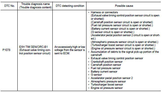
DTC CONFIRMATION PROCEDURE
1.PRECONDITIONING
If DTC Confirmation Procedure has been previously conducted, always perform the following procedure before conducting the next test.
1. Turn ignition switch OFF and wait at least 10 seconds.
2. Turn ignition switch ON.
3. Turn ignition switch OFF and wait at least 10 seconds.
>> GO TO 2.
2.PERFORM DTC CONFIRMATION PROCEDURE
1. Start engine and let it idle for 10 seconds.
2. Check 1st trip DTC.
Is 1st trip DTC detected? YES >> Proceed to EC-313, "Diagnosis Procedure".
NO >> INSPECTION END
Diagnosis Procedure
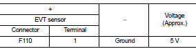
1.CHECK EXHAUST VALVE TIMING (EVT) CONTROL POSITION SENSOR POWER SUPPLY
1. Turn ignition switch OFF.
2. Disconnect exhaust valve timing (EVT) control position sensor harness connector.
3. Turn ignition switch ON.
4. Check the voltage between EVT control position sensor harness connector and ground.
Is the inspection result normal? YES >> GO TO 3.
NO >> GO TO 2.
2.CHECK SENSOR POWER SUPPLY CIRCUIT
1. Turn ignition switch OFF.
2. Disconnect ECM harness connector.
3. Check harness connector for short to power and short to ground, between the following terminals.
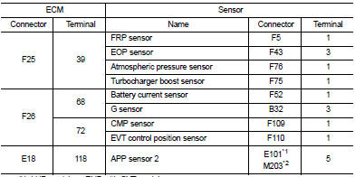
*1: LHD models or RHD with CVT models *2: RHD with M/T models
Is inspection result normal? YES >> Perform the trouble diagnosis for power supply circuit.
NO >> Repair or replace error-detected parts.
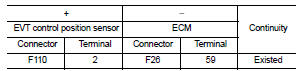
3.CHECK EVT CONTROL POSITION SENSOR GROUND CIRCUIT
1. Turn ignition switch OFF.
2. Disconnect ECM harness connector.
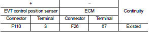
3. Check the continuity between EVT control position sensor harness connector and ECM harness connector.
4. Also check harness for short to power.
Is the inspection result normal? YES >> GO TO 4.
NO >> Repair or replace error-detected parts.
4.CHECK EVT CONTROL POSITION SENSOR INPUT SIGNAL CIRCUIT
1. Disconnect ECM harness connector.
2. Check the continuity between EVT control position sensor harness connector and ECM harness connector.
3. Also check harness for short to ground and to power.
Is the inspection result normal? YES >> GO TO 5.
NO >> Repair or replace error-detected parts.
5.CHECK EVT CONTROL POSITION SENSOR
Check the EVT control position sensor. Refer to EC-315, "Component Inspection".
Is the inspection result normal? YES >> GO TO 6.
NO >> Replace EVT control position sensor. Refer to EM-79, "Removal and Installation".
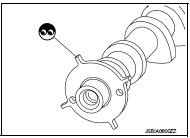
6.CHECK CAMSHAFT (EXT)
Check the following.
• Accumulation of debris to the signal plate of camshaft rear end • Chipping signal plate of camshaft rear end
s the inspection result normal? YES >> Check intermittent incident. Refer to GI-42, "Intermittent Incident".
NO >> Remove debris and clean the signal plate of camshaft rear end or replace camshaft. Refer to EM-79, "Removal and Installation".
Component Inspection
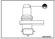
1.EXHAUST VALVE TIMING (EVT) CONTROL POSITION SENSOR-I
1. Turn ignition switch OFF.
2. Disconnect EVT control position sensor harness connector.
3. Loosen the fixing bolt of the sensor.
4. Remove the sensor.
5. Visually check the sensor for chipping.
Is the inspection result normal? YES >> GO TO 2.
NO >> Replace EVT control position sensor. Refer to EM-67, "Exploded View".
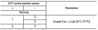
2.EVT CONTROL POSITION SENSOR-II
Check resistance EVT control position sensor terminals as shown below.
Is the inspection result normal? YES >> INSPECTION END
NO >> Replace EVT control position sensor. Refer to EM-67, "Exploded View".
 P0850 PNP switch
Description
For CVT models, transmission range switch is turn ON when the selector lever
is P or N.
For M/T models, park/neutral position (PNP) range switch is ON when the selector
lever is Ne ...
 P1197 out of gas
Description
This diagnosis result is detected when the fuel level of the fuel tank is
extremely low and the engine does not
run normally.
DTC Logic
DTC DETECTION LOGIC
DTC CONFIRMATION PROCED ...
Other materials:
Clutch piping
Exploded View
RS5F92R
1. CSC (Concentric Slave Cylinder)
2. Clutch tube
3. Clutch damper
4. Bracket
5. Master cylinder
RS6F94R
1. CSC (Concentric Slave Cylinder)
2. Clutch tube
3. Clutch damper
4. Bracket
5. Master cylinder
Hydraulic Layout
1. Clutch tube
2. Lock pin
3. ...
Diagnosis and repair work flow
Work Flow
OVERALL SEQUENCE
DETAILED FLOW
1.GET INFORMATION FOR SYMPTOM
1. Get the detailed information from the customer about the symptom (the
condition and the environment
when the incident/malfunction occurred).
2. Check operation condition of the function that is malfunctioning.
> ...
Vehicle-to-vehicle distance control mode
In the vehicle-to-vehicle distance control mode, the Intelligent Cruise Control (ICC) system in your Nissan Leaf automatically monitors and maintains a driver-selected following distance from the vehicle directly ahead. The system dynamically adjusts your speed based on the mov ...
