Nissan Juke Service and Repair Manual : System
System Description
SYSTEM DIAGRAM
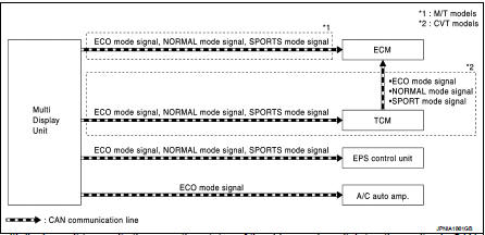
• The multi display unit transmits the operation status of the drive mode switch to other units via CAN communication as the mode signal (refer below).
- NORMAL: ON/OFF
- SPORT: ON/OFF
- ECO: ON/OFF
• Based on the mode signals received from TCM (CVT models) or multi display unit (M/T models) via CAN communication, ECM changes over the throttle position and other characteristics.
• Based on the mode signals received from the multi display unit via CAN communication, TCM changes over the gear shift line and other characteristics.
• Based on the mode signals received from the multi display unit via CAN communication, EPS C/U changes the steering assist characteristic.
• Based on the ECO mode signal received from the multi display unit via CAN communication, the A/C auto amp changes over the set temperature correction.
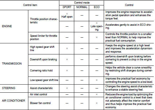
CONTROL DESCRIPTION
• The drive mode switch in the controller of the multi display unit is used to change over the vehicle mode and thus change the control characteristics for the engine, transmission, steering, and air conditioner.
Function Apply List
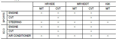
• With the NORMAL mode as the base mode, the control of vehicle characteristics is changed over to the following modes.
- SPORT: The control characteristics for the engine, transmission, and steering system are changed so that a sporty feel is created in the driving behavior.
- ECO: The control characteristics for the engine, transmission, and automatic air conditioner are changed to help improve the practical fuel economy
ENGINE, TRANSMISSION, STEERING, AIR CONDITIONER CONTROL
• For details on the engine control, refer to EC-67, "NISSAN DYNAMIC CONTROL SYSTEM : System Description" (MR16DDT) and EC-486, "NISSAN DYNAMIC CONTROL SYSTEM : System Description" (HR16DE).
• For details on the transmission control, refer to TM-341, "NISSAN DYNAMIC CONTROL SYSTEM : System Description".
• For details on the steering control, refer to STC-8, "EPS SYSTEM : System Description".
• For details on the air conditioner control, refer to HAC-24, "ECO Mode Control".
 Component parts
Component Parts Location
1. A/C auto amp
Refer to HAC-12, "Component Parts
Location"
2. ECM
Refer to EC-25, "ENGINE CONTROL
SYSTEM :
Component Parts Location"
3. TCM
Ref ...
 Handling precaution
NISSAN Dynamic Control System
• The engine torque, engine power, boost pressure, and instantaneous fuel
consumption are provided for
information purposes only. They are not intended to prompt th ...
Other materials:
SRS air bag warning lamp does not turn off
Diagnosis Procedure
1.CHECK AIR BAG MODULE AND SEAT BELT PRE-TENSIONER
Check the deployment of air bag module.
Is air bag module deployed?
YES >> Replace the malfunctioning parts.
NO >> GO TO 2.
2.CHECK AIR BAG FUSE
Check 10 A fuse [No.2, located in fuse block (J/B)].
Is ...
P062f eeprom
DTC Logic
DTC DETECTION LOGIC
DTC CONFIRMATION PROCEDURE
1.PREPARATION BEFORE WORK
If another "DTC CONFIRMATION PROCEDURE" occurs just before, turn ignition
switch OFF and wait for at
least 10 seconds, then perform the next test.
>> GO TO 2.
2.CHECK DTC DETECTION
1. S ...
Warning and indicator lights
Warning/Indicator light (red)
12-volt battery charge warning light
or
Brake warning light
Electric shift control system warning light
or
Electro ...
