Nissan Juke Service and Repair Manual : Component parts
Component Parts Location
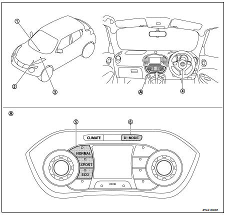
1. A/C auto amp
Refer to HAC-12, "Component Parts
Location"
2. ECM
Refer to EC-25, "ENGINE CONTROL
SYSTEM :
Component Parts Location"
3. TCM
Refer to TM-314, "CVT CONTROL
SYSTEM : Component Parts Location"
4. EPS control unit
Refer to STC-5, "Component Parts
Location"
5. Drive mode switch
• NORMAL switch
• SPORT switch
• ECO switch
6. D-MODE select switch
A. Multi display unit
Component Description
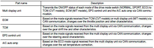
Multi Display Unit
DESCRIPTION
• The multi display unit connects to other units via CAN communication and performs the drive mode control.
• The following 3 drive modes are available, NORMAL, SPORT, and ECO.
• The drive mode can be changed over as desired by pressing the D-MODE select switch. The characteristics of the engine, CVT, steering and air conditioner are changed accordingly.
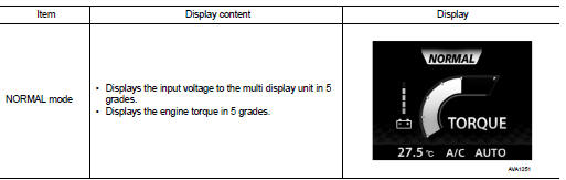
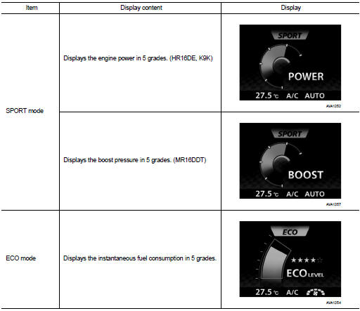
• The display shows the current drive mode (NORMAL, SPORT, ECO) as well as the vehicle information for the mode.
VEHICLE INFORMATION DISPLAY
Drive Mode

 System
System Description
SYSTEM DIAGRAM
• The multi display unit transmits the operation status of the drive mode
switch to other units via CAN communication
as the mode signal (refer below).
- ...
Other materials:
P0705 transmission range switch A
DTC Logic
DTC DETECTION LOGIC
DTC CONFIRMATION PROCEDURE
CAUTION:
Be careful of the driving speed.
1.PREPARATION BEFORE WORK
If another "DTC CONFIRMATION PROCEDURE" occurs just before, turn ignition
switch OFF and wait for at
least 10 seconds, then perform the next test.
> ...
Cooling fan
Component Function Check
1.CHECK COOLING FAN FUNCTION
With CONSULT-III
1. Turn ignition switch ON.
2. Perform “COOLING FAN” in “ACTIVE TEST” mode with CONSULT-III.
3. Touch “LOW” and “Hi” on the CONSULT-III screen.
4. Check that cooling fan operates at each speed.
Without CO ...
Seats
WARNING
Never ride in a moving vehicle with the seatback significantly reclined. This practice is extremely dangerous. When a seat is reclined, the shoulder belt cannot maintain proper contact with your body; in the event of a collision, you could be forcefully t ...
