Nissan Juke Service and Repair Manual : Radiator
Exploded View
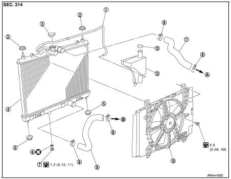
1. Reservoir tank hose
2. Mounting rubber (upper)
3. Radiator tank cap
4. Radiator
5. Mounting rubber (lower)
6. O-ring
7. Drain plug
8. Clamp
9. Radiator hose (lower)
10. Cooling fan assembly
11. Radiator hose (upper)
12. Reservoir tank
13. Reservoir tank cap
A. To water outlet
B. To water inlet
C. To water inlet
 : Always replace after every
disassembly.
 : N·m (kg-m, in-lb)
Removal and Installation
REMOVAL
WARNING:
• Never remove radiator cap when engine is hot. Serious burns may occur from
high-pressure engine
coolant escaping from radiator.
• Wrap a thick cloth around the radiator cap. Slowly turn it a quarter of a turn to release built-up pressure.
Then turn it all the way.
1. Drain engine coolant from radiator. Refer to CO-37, "Draining".
CAUTION:
• Perform this step when the engine is cold.
• Never spill engine coolant on drive belt.
2. Remove air duct (inlet). Refer to EM-161, "Exploded View".
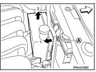
3. Remove reservoir tank as follows: a. Disconnect reservoir tank hose.
b. Release the tab (A) in the direction shown by the arrow (
).
c. Lift up and remove the reservoir tank with tab released.
4. Remove radiator hose (upper and lower).
5. Disconnect harness connector from fan motor, and move harness aside.
6. Remove cooling fan assembly.
CAUTION:
Be careful not to damage or scratch the radiator core.
7. Remove the following parts.
• Front grille assembly. Refer to EXT-18, "Removal and Installation".
• Front bumper fasica assembly. Refer to EXT-13, "Removal and Installation" • Front combination lamp assembly (LH and RH). Refer to EXL-91, "Removal and Installation".
8. Remove radiator core support (upper). Refer to DLK-147, "HR16DE : Removal and Installation" (WITH IKEY &SUPER LOCK) or DLK-310, "HR16DE : Removal and Installation" (WITH I-KEY WITHOUT SUPER LOCK) orDLK-445, "HR16DE : Removal and Installation" (WITHOUT I-KEY &WITH SUPER LOCK) DLK- 561, "HR16DE : Removal and Installation" (WITHOUT I-KEY & SUPER LOCK).
9. Remove the radiator (1) from bottom of the vehicle.
2 : Condenser assembly
 : Vehicle front
CAUTION:
Be careful not to damage radiator core and condenser assembly core.
INSTALLATION
Install in the reverse order of removal.
Radiator
NOTE
:
When installing radiator core support (upper), check that both upper and lower
mounts of radiator and air conditioner
condenser are inserted in the mounting holes of radiator core support (upper,
lower).
CAUTION:
Use genuine mounting bolts for the cooling fan assembly and strictly observe the
tightening torque.
(Breakage prevention for radiator)
Reservoir tank
NOTE
:
• Insert reservoir tank straight into the mounting location and check by the
feel that the pawl is securely fastened.
• Pull reservoir tank upward to check that it does not come off.
Radiator hose
NOTE
:
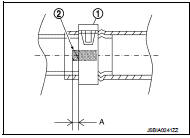
Insert the radiator hose (1) all the way to the stopper (2) or by 33 mm (1.30
in) (hose without a stopper).
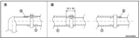
Unit: mm (in)
A. Radiator side
B. Engine side
• For the orientation of the hose clamp pawl, refer to the figure.
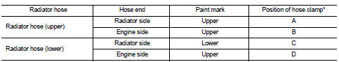
*: Refer to the illustrations for the specific position each hose clamp tab.
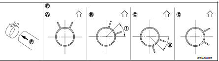
E. View E f. 45° g, 45°
 : Vehicle upper
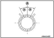
• The angle (b) created by the hose clamp pawl and the specified line (A) must be within ±30 as shown in the figure.
• To install hose clamps (1), check that the dimension (A) from the end of the hose clamp on the radiator hose to the hose clamp is within the reference value.
Dimension “A” : (−1) – (+1) mm
Inspection
INSPECTION AFTER INSTALLATION
• Check for leakage of engine coolant using the radiator cap tester adapter (commercial service tool) and the radiator cap tester (commercial service tool). Refer to CO-37, "Inspection".
• Start and warm up the engine. Check visually that there is no leakage of engine coolant.

 Cooling fan
Exploded View
1. Fan motor
2. Fan shroud
3. Cooling fan
A. Apply on fan motor shaft
: Apply genuine high strength
thread locking sealant or equivalent.
: N·m (kg-m, in-lb)
Removal and I ...
Other materials:
Magnet clutch
Component Function Check
1.CHECK MAGNET CLUTCH OPERATION
Perform auto active test of IPDM E/R. Refer to PCS-12, "Diagnosis
Description" (with Intelligent Key) or PCS-
43, "Diagnosis Description" (without Intelligent Key).
Does it operate normally?
YES >> INSPECTION ...
A-bag branch line circuit
Diagnosis Procedure
WARNING:
• Before servicing, turn ignition switch OFF, disconnect battery negative
terminal, and wait 3 minutes
or more. (To discharge backup capacitor.)
• Never use unspecified tester or other measuring device.
1.CHECK CONNECTOR
1. Turn the ignition switch OFF.
2. D ...
Heated seat switch
Exploded View
1. Heated seat swich
2. Switch bracket
3. Console switch finisher
Removal and Installation
REMOVAL
CAUTION:
When removing and installing, use shop cloths to protect from damage.
1. Remove the console switch finisher. Refer to IP-23, "Removal and
Installation".
...
