Nissan Juke Service and Repair Manual : P1205 exhaust fuel injector
DTC Logic
DTC DETECTION LOGIC
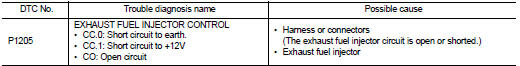
Diagnosis Procedure
1.CHECK EXHAUST FUEL INJECTOR POWER SUPPLY CIRCUIT FOR OPEN AND SHORT
1. Turn ignition switch OFF.
2. Disconnect exhaust fuel injector harness connector.
3. Turn ignition switch ON.
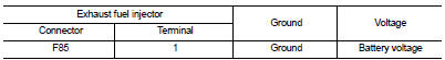
4. Check the voltage between exhaust fuel injector harness connector and ground.
Is the inspection result normal? YES >> GO TO 3.
NO >> GO TO 2.
2.DETECT MALFUNCTIONING PART
Check the following.
• Harness connectors E8, F1 • Harness for open or short between IPDM E/R and exhaust fuel injector
>> Repair open circuit or short to ground or short to power in harness or connectors.
3.CHECK FUEL INJECTOR OUTPUT SIGNAL CIRCUIT FOR OPEN AND SHORT
1. Turn ignition switch OFF.
2. Disconnect ECM harness connector.
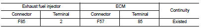
3. Check the continuity between exhaust fuel injector harness connector and ECM harness connector.
4. Also check harness for short to ground and short to power.
Is the inspection result normal? YES >> GO TO 4.
NO >> Repair open circuit or short to ground or short to power in harness or connectors.
4.CHECK EXHAUST FUEL INJECTOR
Refer to EC-983, "Component Inspection".
Is the inspection result normal? YES >> GO TO 5.
NO >> Replace exhaust fuel injector.
5.CHECK INTERMITTENT INCIDENT
Refer to GI-42, "Intermittent Incident", ???INCIDENT SIMULATION TESTS??? and ???GROUND INSPECTION???.
>> INSPECTION END
Component Inspection
1.CHECK EXHAUST FUEL INJECTOR
1. Turn ignition switch OFF.
2. Disconnect exhaust fuel injector harness connector.
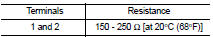
3. Check resistance between exhaust fuel injector terminals as follows.
Is the inspection result normal? YES >> INSPECTION END
NO >> Replace exhaust fuel injector.
 P0833 CPP switch
DTC Logic
DTC DETECTION LOGIC
Diagnosis Procedure
1.CHECK CLUTCH PEDAL POSITION SWITCH GROUND CIRCUIT FOR OPEN AND SHORT
1. Turn ignition switch OFF.
2. Disconnect clutch pedal position switch ...
 P1525 communication circuit for ASCD and speed limiter
DTC Logic
DTC DETECTION LOGIC
...
Other materials:
Except for M/T models
Except for M/T models : Description
ECM receives a G sensor signal from TCM via CAN communication to switch
combustion for the direct injection
gasoline system. For the direct injection gasoline system, refer toEC-48,
"DIRECT INJECTION GASOLINE
SYSTEM : System Description".
Except ...
NISSAN customer care program
NISSAN CARES ...
Both NISSAN and your NISSAN dealer are dedicated to serving all your automotive
needs. Your satisfaction with your vehicle and your NISSAN dealer are our primary
concerns. Your NISSAN dealer is always available to assist you with all your automobile
sales and service needs.
...
Precaution for Supplemental Restraint System (SRS) "AIR BAG" and "SEAT BELT
PRE-TENSIONER"
The Supplemental Restraint System such as “AIR BAG” and “SEAT BELT PRE-TENSIONER”,
used along
with a front seat belt, helps to reduce the risk or severity of injury to the
driver and front passenger for certain
types of collision. Information necessary to service the system safely is
...
