Nissan Juke Service and Repair Manual : Wiring diagram
EXTERIOR LIGHTING SYSTEM
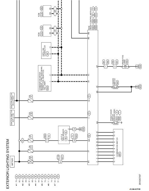
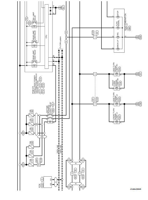
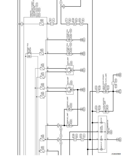
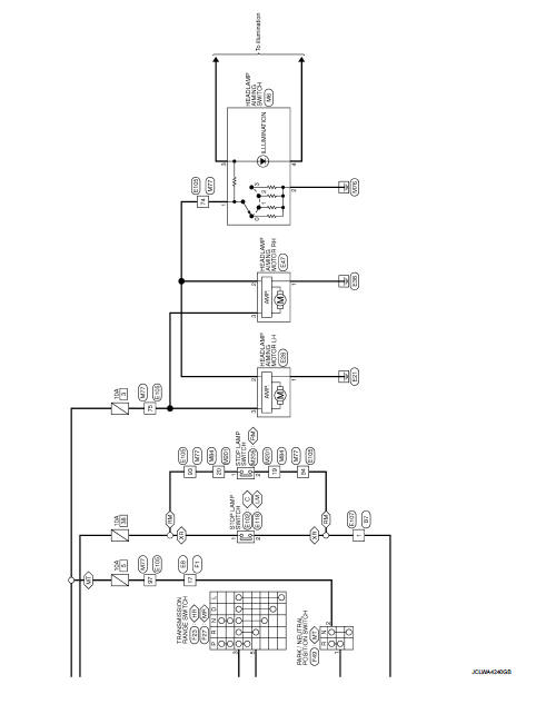
Wiring Diagram
For connector terminal arrangemants, harness layouts, and alphabets in a
 (option abbreviation: if not
described in wiring diagram), refer to GI-12, "Connector Information/Explanation
of Option Abbreviation".
 Ecu diagnosis informatioN
BCM, IPDM E/R
List of ECU Reference
WITH INTELLIGENT KEY
WITHOUT INTELLIGENT KEY
...
 Basic inspection
DIAGNOSIS AND REPAIR WORKFLOW
Work Flow
OVERALL SEQUENCE
DETAILED FLOW
1.INTERVIEW FOR MALFUNCTION
Interview the symptom to the customer.
>> GO TO 2.
2.SYMPTOM CHECK
Check the sympto ...
Other materials:
Precaution Necessary for Steering Wheel Rotation after Battery Disconnect
NOTE:
• Before removing and installing any control units, first turn the ignition
switch to the LOCK position, then disconnect
both battery cables.
• After finishing work, confirm that all control unit connectors are connected
properly, then re-connect both
battery cables.
• Always us ...
Intelligent Driver Alertness (I-DA)
WARNING
The Intelligent Driver Alertness (I-DA) system is a supportive technology designed to monitor driving patterns; relying on this system to manage your fatigue or failing to adhere to the provided instructions could result in an accident, potentially causing serious injury or death.
...
Hazard warning flasher switch
Activate the hazard warning flasher switch to alert other motorists when you are required to stop or park your Nissan Leaf under emergency conditions. Once engaged, all exterior turn signal lamps will flash simultaneously, providing high visibility to surrounding traffic.
...
