Nissan Juke Service and Repair Manual : Stall test
Work Procedure
INSPECTION
1. Check the engine oil level. Replenish if necessary. Refer to LU-25, "Inspection".
2. Check for leak of the CVT fluid. Refer to TM-480, "Inspection".
3. Drive for about 10 minutes to warm up the vehicle so that the CVT fluid temperature is 50 to 80°C (122 to 176°F).
4. Be sure to apply the parking brake and block the tires.
5. Start the engine, depress the brake pedal and put the selector lever to the D position.
6. While depressing the brake pedal, depress the accelerator pedal gradually.
7. Read the stall speed quickly. Then, release your foot from the accelerator pedal quickly.
CAUTION:
Never depress the accelerator pedal for 5 seconds or more during the test.
Stall speed : Refer to TM-512, "Stall Speed".
8. Place the selector lever in the N position.
9. Cool the CVT fluid.
CAUTION:
Run the engine with the idle speed for at least 1 minute.
10. Put the selector lever to the R position and perform Step 6 to Step 9 again.
NARROWING-DOWN MALFUNCTIONING PARTS
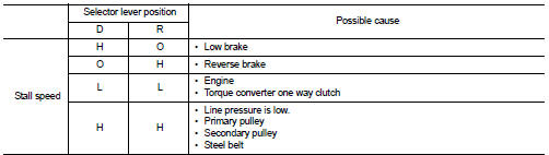
O: Within the stall speed standard value H: Stall speed is higher than the standard value.
L: Stall speed is lower than the standard value.
 CVT fluid
Replacement
CVT fluid : Refer to TM-512, "General Specification".
Fluid capacity : Refer to TM-512, "General Specificatio
CAUTION:
• Use only Genuine NISSAN CVT Fluid NS-2. Using ...
 Line pressure test
Work Procedure
INSPECTION
1. Check the engine oil level. Replenish if necessary. LU-25, "Inspection".
2. Check for leak of the CVT fluid. Refer to TM-480, "Inspection".
3. Driv ...
Other materials:
P1212 TCS communication line
Description
This CAN communication line is used to control the smooth engine operation
during the TCS operation. Pulse
signals are exchanged between ECM and “ABS actuator and electric unit (control
unit)”.
Be sure to erase the malfunction information such as DTC not only for “ABS
ac ...
Component parts
Starting system (with intelligent key) : Component Parts Location
1. IPDM E/R
Refer to PCS-5, "Component Parts
Location".
2. Transmission range switch (CVT
models)
Refer to TM-131, "CVT CONTROL
SYSTEM : Component Parts Location"
(MR16DDT), TM-314, "CVT
CONTROL SYS ...
Power supply and ground circuit
Navi control unit
NAVI CONTROL UNIT : Diagnosis Procedure
1.CHECK FUSE
Check for blown fuses.
Is inspection result OK?
YES >> GO TO 2.
NO >> Be sure to eliminate cause of malfunction before installing new fuse.
2.CHECK POWER SUPPLY CIRCUIT
Check voltage between NAVI control ...
