Nissan Juke Service and Repair Manual : P0833 CPP switch
DTC Logic
DTC DETECTION LOGIC
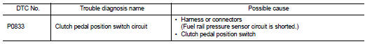
Diagnosis Procedure
1.CHECK CLUTCH PEDAL POSITION SWITCH GROUND CIRCUIT FOR OPEN AND SHORT
1. Turn ignition switch OFF.
2. Disconnect clutch pedal position switch harness connector.
3. Check the continuity between clutch pedal position switch harness connector and ground.
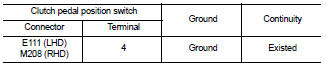
4. Also check harness for short to power.
Is the inspection result normal? YES >> GO TO 2.
NO >> Repair open circuit or short to power in harness or connectors.
2.CHECK CLUTCH PEDAL POSITION SWITCH INPUT SIGNAL CIRCUIT FOR OPEN AND SHORT
1. Disconnect ECM harness connector.
2. Check the continuity between clutch pedal position switch harness connector and ECM harness connector.
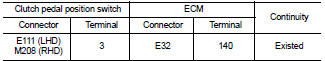
3. Also check harness for short to ground and short to power.
Is the inspection result normal? YES >> GO TO 3.
NO >> Repair open circuit or short to ground or short to power in harness or connectors.
3.CHECK CLUTCH PEDAL POSITION SWITCH
Refer to EC-981, "Component Inspection".
Is the inspection result normal? YES >> GO TO 4.
NO >> Replace clutch pedal position switch.
4.CHECK INTERMITTENT INCIDENT
Refer to GI-42, "Intermittent Incident".
>> INSPECTION END
Component Inspection
1.CHECK CLUTCH PEDAL POSITION SWITCH-I
1. Turn ignition switch OFF.
2. Disconnect clutch pedal position switch harness connector.
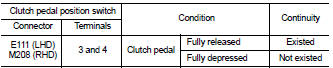
3. Check the continuity between clutch pedal position switch terminals under the following conditions.
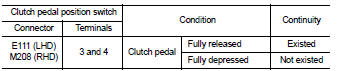
Is the inspection result normal? YES >> INSPECTION END
NO >> GO TO 2.
2.CHECK CLUTCH PEDAL POSITION SWITCH-II
1. Adjust clutch pedal position switch installation. Refer to CL-7, "Inspection and Adjustment".
2. Check the continuity between clutch pedal position switch terminals under the following conditions.
Is the inspection result normal? YES >> INSPECTION END
NO >> Replace clutch pedal position switch.
 P0697 sensor power supply
DTC Logic
DTC DETECTION LOGIC
Diagnosis Procedure
1.CHECK GROUND CONNECTION
1. Turn ignition switch OFF and wait at least 4 minutes.
2. Check ground connection E38. Refer to Ground Inspection i ...
 P1205 exhaust fuel injector
DTC Logic
DTC DETECTION LOGIC
Diagnosis Procedure
1.CHECK EXHAUST FUEL INJECTOR POWER SUPPLY CIRCUIT FOR OPEN AND SHORT
1. Turn ignition switch OFF.
2. Disconnect exhaust fuel injector harness ...
Other materials:
Steering switch signal A circuit
Description
Transmits the steering switch signal to NAVI control unit.
Diagnosis Procedure
1.CHECK STEERING SWITCH SIGNAL A CIRCUIT
1. Disconnect NAVI control unit connector and spiral cable connector.
2. Check continuity between NAVI control unit harness connector and spiral cable
harness co ...
Door does not lock/unlock with door lock and unlock
switch
All door
ALL DOOR : Description
All doors do not lock/unlock using door lock and unlock switch.
ALL DOOR : Diagnosis Procedure
1.CHECK DOOR LOCK AND UNLOCK SWITCH
Check door lock and unlock switch. Refer to the following.
• Driver side: Refer to DLK-391, "DRIVER SIDE : Component Funct ...
Vehicle speed sensing auto lock operation does not operate
Diagnosis Procedure
1.CHECK “AUTOMATIC LOCK/UNLOCK SELECT” SETTING IN “WORK SUPPORT”
1. Select “DOOR LOCK” of “BCM” using CONSULT-III.
2. Select “AUTOMATIC LOCK/UNLOCK SELECT” in “WORK SUPPORT” mode.
3. Check “AUTOMATIC LOCK/UNLOCK SELECT” in “WORK SUPPORT”.
Re ...
