Nissan Juke Service and Repair Manual : Cooling fan
Exploded View
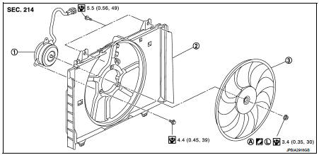
1. Fan motor
2. Fan shroud
3. Cooling fan
A. Apply on fan motor shaft
 : Apply genuine high strength
thread locking sealant or equivalent.
 : N·m (kg-m, in-lb)
Removal and Installation
REMOVAL
1. Drain engine coolant from radiator. Refer to CO-37, "Draining".
CAUTION:
• Perform this step engine is cold.
• Never spill engine coolant on drive belt.
2. Remove air duct (inlet) and resonator assembly. Refer to EM-161, "Removal and Installation".
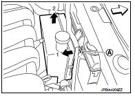
3. Remove reservoir tank as follows: a. Disconnect reservoir tank hose.
b. Release the tab (A) in the direction shown by the arrow (
 ).
).
c. Lift up and remove the reservoir tank with the tab released.
4. Remove radiator hose (upper). Refer to CO-42, "Exploded View".
5. Disconnect harness connector from fan motor, and move harness to aside.
6. Remove cooling fan assembly.
CAUTION:
Be careful not to damage or scratch on radiator core when removing.
INSTALLATION
Note the following, and install in the reverse order of removal.
CAUTION:
Only use genuine parts for fan shroud mounting bolt and observe the specified
torque (to prevent
radiator from being damaged).
NOTE:
Cooling fan is controlled by ECM. For details, Refer to EC-774, "Component Function Check".
Disassembly and Assembly
DISASSEMBLY
1. Remove cooling fan mounting nut, and then remove the cooling fan.
2. Remove fan motor.
ASSEMBLY
Note the following, and assemble in the reverse order of disassembly.
• Apply genuine high strength thread locking sealant on fan motor shaft.
Inspection
Cooling Fan
Inspect cooling fan for crack or unusual bend.
• If anything is found, replace cooling fan.
 Radiator
Exploded View
1. Reservoir tank hose
2. Mounting rubber (upper)
3. Radiator tank cap
4. Radiator
5. Mounting rubber (lower)
6. O-ring
7. Drain plug
8. Clamp
9. Radiator hose (lower)
...
 Water pump
Exploded View
1. Gasket
2. Water pump
3. Water pump pulley
: Always replace after every
disassembly.
: N·m (kg-m, in-lb)
: N·m (kg-m, ft-lb)
Removal and Installation
REMOVAL
1. Drain ...
Other materials:
Additional service when removing battery negative terminal
Description
• The NAVI control unit is equipped with the anti-theft system.
• The NAVI control unit operates after authenticating a fixed four-digit
anti-theft code.
• After removing the battery of the NAVI control unit, the authentication of the
anti-theft code is required.
Work Proce ...
P2A00 A/F sensor 1
DTC Logic
DTC DETECTION LOGIC
To judge the malfunction, the A/F signal computed by ECM from the A/F sensor
1 signal is monitored so it will
not shift to LEAN side or RICH side.
DTC CONFIRMATION PROCEDURE
1.PRECONDITIONING
If DTC Confirmation Procedure has been previously conducted, always ...
Wiper and washer switch
WARNING
When driving your Nissan Leaf in freezing conditions, please be aware that washer solution can freeze rapidly upon contact with a cold windshield, severely obscuring your view and creating a significant safety hazard. To ensure optimal visibility and prevent accidents, always activate t ...
