Nissan Juke Service and Repair Manual : Removal and Installation
REMOVAL
1. Separate the rear propeller shaft. Refer to DLN-121, "Removal and Installation".
2. Remove right side drive shaft. Refer to FAX-24, "RIGHT SIDE : Removal and Installation".
3. Remove catalyst convertor support bracket (RH). EM-35, "4WD : Removal and Installation".
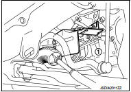
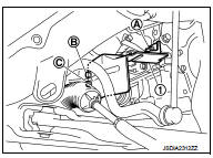
4. Remove heat insulator (1).
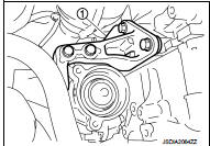
5. Remove transfer gusset (1).
6. Remove catalyst convertor upport bracket rear. EM-59, "4WD : Removal and Installation".
7. Remove rear torque rod and rear torque rod bracket. Refer to EM-59, "4WD : Removal and Installation".
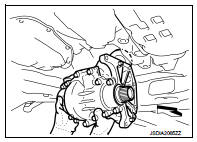
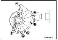
8. Remove the mounting bolts of transaxle assembly and transfer assembly.
9. Remove transfer assembly from the vehicle.
 : Vehicle front
CAUTION:
Never damage ring gear shaft.
INSTALLATION
Note the following, and install in the reverse order of removal.
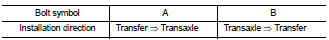
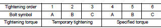
• When installing the transfer to the transaxle, install the mounting bolts following the standard below.
CAUTION:
• When installing transfer assembly to transaxle assembly,
replace the side oil seal (transfer joint). Refer to TM-292,
"Removal and Installation".
• Never damage side oil seal (the joint part of transfer).
• When installing heat insulator (1), install the mounting bolts and nut following procedure.
• Check oil level and check for oil leakage after installation. Refer to DLN-90, "Inspection".
 Exploded View
1. Transfer gusset
2. Transfer assembly
3. Heat insulator
: Vehicle front
: N·m (kg-m, ft-lb)
...

Other materials:
Components
• THE LARGE ILLUSTRATIONS are exploded views (see the following) and
contain tightening torques, lubrication
points, section number of the PARTS CATALOG (e.g. SEC. 440) and other
information necessary to
perform repairs.
The illustrations should be used in reference to service matters onl ...
ICC system limitations
WARNING
The following points outline the operational boundaries of the Intelligent Cruise Control (ICC) system. Operating your Nissan Leaf without regard for these limitations can lead to a serious accident, resulting in injury or death:
The ICC system is optimized for travel on ...
Basic inspection
DIAGNOSIS AND REPAIR WORKFLOW (METER SYSTEM)
Work flow
OVERALL SEQUENCE
• Reference 1···MWI-22, "On Board Diagnosis Function".
• Reference 2···MWI-36, "DTC Index".
• Reference 3···MWI-51, "COMBINATION METER : Diagnosis Procedure".
DETAILED FLOW
...
