Nissan Juke Owners Manual : Forward-facing child restraint installation using LATCH
Refer to all Warnings and Cautions in the ŌĆ£Child safetyŌĆØ and ŌĆ£Child restraintsŌĆØ sections before installing a child restraint.
Follow these steps to install a forward-facing child restraint using the LATCH system:
1. Position the child restraint on the seat.
Always follow the child restraint manufacturerŌĆÖs instructions.
Forward-facing web-mounted ŌĆö step 2
2. Secure the child restraint anchor attachments to the LATCH lower anchors. Check to make sure the LATCH attachment is properly attached to the lower anchors.
If the child restraint is equipped with a top tether strap, route the top tether strap and secure the tether strap to the tether anchor point. See ŌĆ£Installing top tether strapŌĆØ (P.1- 32). Do not install child restraints that require the use of a top tether strap in seating positions that do not have a top tether anchor.
Forward-facing rigid-mounted ŌĆö step 2
3. The back of the child restraint should be secured against the vehicle seatback.
If necessary, adjust or remove the head restraint to obtain the correct child restraint fit. If the head restraint is removed, store it in a secure place. Be sure to reinstall the head restraint when the child restraint is removed. See ŌĆ£Head restraints/HeadrestsŌĆØ for head restraint adjustment information.
If the seating position does not have a head restraint and it is interfering with the proper child restraint fit, try another seating position or a different child restraint.
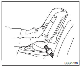
Forward-facing ŌĆö step 4
4. For child restraints that are equipped with webbing-mounted attachments, remove any additional slack from the anchor attachments.
Press downward and rearward firmly in the center of the child restraint with your knee to compress the vehicle seat cushion and seatback while tightening the webbing of the anchor attachments.
5. Tighten the tether strap according to the manufacturerŌĆÖs instructions to remove any slack.
Forward-facing ŌĆö step 6
6. After attaching the child restraint, test it before you place the child in it. Push it from side to side while holding the child restraint near the LATCH attachment path. The child restraint should not move more than 1 inch (25 mm), from side to side. Try to tug it forward and check to see if the LATCH attachment holds the restraint in place. If the restraint is not secure, tighten the LATCH attachment as necessary, or put the restraint in another seat and test it again. You may need to try a different child restraint. Not all child restraints fit in all types of vehicles.
7. Check to make sure the child restraint is properly secured prior to each use. If the child restraint is loose, repeat steps 1 through 6.
 Rear-facing child restraint installation using the seat belts
WARNING
The three-point seat belt with Automatic Locking Retractor (ALR) must be used
when installing a child restraint.
Failure to use the ALR mode will result in the child restraint not being ...
 Forward-facing child restraint installation using the seat belts
WARNING
The three-point seat belt with Automatic Locking Retractor (ALR) must be used
when installing a child restraint.
Failure to use the ALR mode will result in the child restraint not being pr ...
Other materials:
Inspection
LEVEL
ŌĆó Check that the reservoir tank engine coolant level is within the
ŌĆ£MINŌĆØ to ŌĆ£MAXŌĆØ when the engine is cool.
A : MAX
B : MIN
ŌĆó Adjust the engine coolant level if necessary.
LEAKAGE
ŌĆó To check for leakage, apply pressure to the cooling system with the
radiator cap tester ( ...
Drive pinion
Exploded View
1. Pinion lock nut
2. Companion flange
3. Drive pion oil seal
4. Pinon rear bearing
5. Transfer case
6. Gasket
7. Filler plug
8. Collapsible spacer
9. Drive pinion adjust shim
10. Drive pinion
11. Pinion front bearing
12. Ring gear
13. Ring gear shaft
14. Ring ...
G sensor
Exploded View
1. G sensor
: Vehicle front
: N┬Ęm (kg-m, in-lb)
Removal and Installation
CAUTION:
ŌĆó Never drop or strike G sensor, because it has little tolerance for impact.
ŌĆó Never use a power tool to avoid impact.
REMOVAL
1. Disconnect the battery cable from the negative terminal. R ...
