
Nissan Juke Owners Manual : Rear-facing child restraint installation using the seat belts
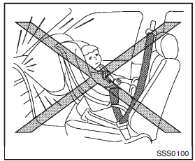
WARNING
The three-point seat belt with Automatic Locking Retractor (ALR) must be used when installing a child restraint.
Failure to use the ALR mode will result in the child restraint not being properly secured. The restraint could tip over or be loose and cause injury to a child in a sudden stop or collision. Also, it can change the operation of the front passenger air bag. See “Front passenger air bag and status light� .
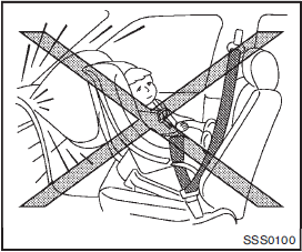
Rear-facing — step 1
Refer to all Warnings and Cautions in the “Child safety� and “Child restraints� before installing a child restraint.
Follow these steps to install a rear-facing child restraint using the vehicle seat belts in the rear seats:
1. Child restraints for infants must be used in the rear-facing direction and therefore must not be used in the front seat. Position the child restraint on the seat.
Always follow the restraint manufacturer’s instructions.
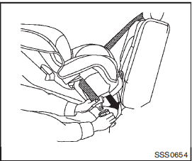
Rear-facing — step 2
2. Route the seat belt tongue through the child restraint and insert it into the buckle until you hear and feel the latch engage. Be sure to follow the child restraint manufacturer’s instructions for belt routing.
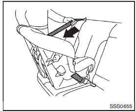
Rear-facing — step 3
3. Pull the shoulder belt until the belt is fully extended. At this time, the seat belt retractor is in the Automatic Locking Retractor (ALR) mode (child restraint mode). It reverts to the Emergency Locking Retractor (ELR) mode when the seat belt is fully retracted.

Rear-facing — step 4
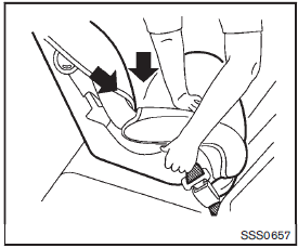
4. Allow the seat belt to retract. Pull up on the shoulder belt to remove any slack in the belt.
Rear-facing — step 5
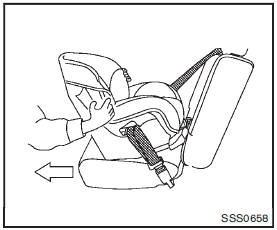
5. Remove any additional slack from the seat belt; press downward and rearward firmly in the center of the child restraint to compress the vehicle seat cushion and seatback while pulling up on the seat belt.
Rear-facing — step 6
6. After attaching the child restraint, test it before you place the child in it. Push it from side to side while holding the child restraint near the seat belt path. The child restraint should not move more than 1 inch (25 mm), from side to side. Try to tug it forward and check to see if the belt holds the restraint in place. If the restraint is not secure, tighten the seat belt as necessary, or put the restraint in another seat and test it again.
You may need to try a different child restraint. Not all child restraints fit in all types of vehicles.
7. Check to make sure that the child restraint is properly secured prior to each use. If the seat belt is not locked, repeat steps 1 through 6.
After the child restraint is removed and the seat belt fully retracted, the ALR mode (child restraint mode) is canceled.
 Rear-facing child restraint installation using LATCH
Refer to all Warnings and Cautions in the “Child safety� and “Child restraints�
sections before installing a child restraint.
Follow these steps to install a rear-facing child restraint usi ...
 Forward-facing child restraint installation using LATCH
Refer to all Warnings and Cautions in the “Child safety� and “Child restraints�
sections before installing a child restraint.
Follow these steps to install a forward-facing child restraint ...
Other materials:
Wiring diagram
NISSAN DYNAMIC CONTROL SYSTEM
Wiring Diagram
For connector terminal arrangements, harness layouts, and alphabets in a
(option abbreviation; if not
described in wiring diagram), refer to GI-12, "Connector Information/Explanation
of Option Abbreviation".
...
Meters and gauges
1. Tachometer
2. Engine coolant temperature gauge
3. Vehicle information display
— Odometer/twin trip odometer
— Trip computer
— Torque vectoring AWD (AWD model)
— Outside air temperature
4. Fuel gauge
5. Speedometer
6. Warning/indicator lights
7. Instrument brightness control kn ...
Main line between DLC and A-bag circuit
Diagnosis Procedure
1.CHECK HARNESS CONTINUITY (OPEN CIRCUIT)
1. Turn the ignition switch OFF.
2. Disconnect the battery cable from the negative terminal.
3. Disconnect the BCM harness connector.
4. Check the continuity between the data link connector and the BCM harness
connector.
- With In ...
