Nissan Juke Service and Repair Manual : BCM branch line circuit
Diagnosis Procedure
1.CHECK CONNECTOR
1. Turn the ignition switch OFF.
2. Disconnect the battery cable from the negative terminal.
3. Check the terminals and connectors of the BCM for damage, bend and loose connection (unit side and connector side).
Is the inspection result normal? YES >> GO TO 2.
NO >> Repair the terminal and connector.
2.CHECK HARNESS FOR OPEN CIRCUIT
1. Disconnect the connector of BCM.
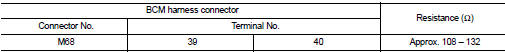
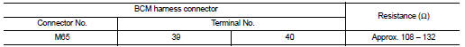
2. Check the resistance between the BCM harness connector terminals.
- Models with Intelligent Key system
- Models without Intelligent Key system
Is the measurement value within the specification? YES >> GO TO 3.
NO >> Repair the BCM branch line.
3.CHECK POWER SUPPLY AND GROUND CIRCUIT
Check the power supply and the ground circuit of the BCM. Refer to the following.
• Models with Intelligent Key system: BCS-87, "Diagnosis Procedure" • Models without Intelligent Key system: BCS-155, "Diagnosis Procedure"
Is the inspection result normal? YES (Present error)>>Replace the BCM. Refer to the following.
• Models with Intelligent Key system: BCS-93, "Removal and Installation" • Models without Intelligent Key system: BCS-161, "Removal and Installation"
YES (Past error)>>Error was detected in the BCM branch line.
NO >> Repair the power supply and the ground circuit.
 PTC branch line circuit
Diagnosis Procedure
1.CHECK CONNECTOR
1. Turn the ignition switch OFF.
2. Disconnect the battery cable from the negative terminal.
3. Check the terminals and connectors of the PTC heater control u ...
 Can communication circuit
Diagnosis Procedure
1.CONNECTOR INSPECTION
1. Turn the ignition switch OFF.
2. Disconnect the battery cable from the negative terminal.
3. Disconnect all the unit connectors on CAN communication s ...
Other materials:
Combination switch
Exploded View
1. Combination switch
2. Combination switch connector
Removal and Installation
REMOVAL
1. Remove steering column cover. Refer to IP-13, "Removal and
Installation".
2. Remove screws.
3. Disconnect the connector.
4. Pull up the combination switch to remove it.
I ...
Air conditioning system refrigerant and lubricant recommendations
The air conditioning system in your NISSAN vehicle must be charged with the
refrigerant HFC-134a (R-134a) and the oil, NISSAN A/C system oil Type R or the exact
equivalents.
CAUTION
The use of any other refrigerant or oil will cause severe damage to the air
conditioning system and will requi ...
Hood lock
Exploded View
1. Hood lock control cable assembly
2. Hood lock assembly
: Clip
: N·m (kg-m, ft-lb)
: Body grease
Hood lock
HOOD LOCK : Removal and Installation
REMOVAL
1. Remove front center grille. Refer to EXT-18, "Removal and Installation".
2. Remove crash zone sensor. Ref ...
