Nissan Juke Service and Repair Manual : Can communication circuit
Diagnosis Procedure
1.CONNECTOR INSPECTION
1. Turn the ignition switch OFF.
2. Disconnect the battery cable from the negative terminal.
3. Disconnect all the unit connectors on CAN communication system.
4. Check terminals and connectors for damage, bend and loose connection.
Is the inspection result normal? YES >> GO TO 2.
NO >> Repair the terminal and connector.
2.CHECK HARNESS CONTINUITY (SHORT CIRCUIT)
Check the continuity between the data link connector terminals.
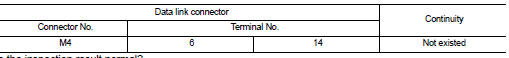
Is the inspection result normal? YES >> GO TO 3.
NO >> Check the harness and repair the root cause.
3.CHECK HARNESS CONTINUITY (SHORT CIRCUIT)
Check the continuity between the data link connector and the ground.
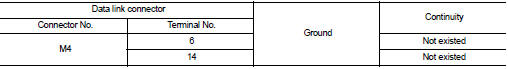
Is the inspection result normal? YES >> GO TO 4.
NO >> Check the harness and repair the root cause.
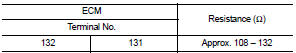
4.CHECK ECM AND BCM TERMINATION CIRCUIT
1. Remove the ECM and the BCM.
2. Check the resistance between the ECM terminals.
- HR16DE models
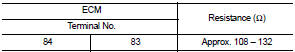
- MR16DDT models
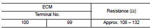
- K9K models
3. Check the resistance between the BCM terminals.
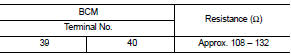
Is the measurement value within the specification? YES >> GO TO 5.
NO >> Replace the ECM and/or the BCM.
5.CHECK SYMPTOM
Connect all the connectors. Check if the symptoms described in the “Symptom (Results from interview with customer)” are reproduced.
Inspection result Reproduced>>GO TO 6.
Non-reproduced>>Start the diagnosis again. Follow the trouble diagnosis procedure when past error is detected.
6.CHECK UNIT REPRODUCTION
Perform the reproduction test as per the following procedure for each unit.
1. Turn the ignition switch OFF.
2. Disconnect the battery cable from the negative terminal.
3. Disconnect one of the unit connectors of CAN communication system.
NOTE
:
ECM and BCM have a termination circuit. Check other units first.
4. Connect the battery cable to the negative terminal. Check if the symptoms described in the “Symptom (Results from interview with customer)” are reproduced.
NOTE
:
Although unit-related error symptoms occur, do not confuse them with other
symptoms.
Inspection result Reproduced>>Connect the connector. Check other units as per the above procedure.
Non-reproduced>>Replace the unit whose connector was disconnected.
 BCM branch line circuit
Diagnosis Procedure
1.CHECK CONNECTOR
1. Turn the ignition switch OFF.
2. Disconnect the battery cable from the negative terminal.
3. Check the terminals and connectors of the BCM for damage, bend ...
 LAN System can system (type 1)
DTC/circuit diagnosis
Main line between IPDM-E and DLC circuit
Diagnosis Procedure
1.CHECK CONNECTOR
1. Turn the ignition switch OFF.
2. Disconnect the battery cable from the negative terminal.
...
Other materials:
B26F7 BCM
DTC Logic
DTC DETECTION LOGIC
DTC CONFIRMATION PROCEDURE
1.PERFORM DTC CONFIRMATION PROCEDURE
1. Press door request switch.
2. Turn ignition switch ON.
3. Check DTC in “Self Diagnostic Result” mode of “BCM” using CONSULT-III.
Is DTC detected?
YES >> Go to SEC-127, "Dia ...
P0603 ECM power supply
DTC Logic
DTC DETECTION LOGIC
DTC CONFIRMATION PROCEDURE
1.PRECONDITIONING
If DTC Confirmation Procedure has been previously conducted, always perform
the following procedure
before conducting the next test.
1. Turn ignition switch OFF and wait at least 10 seconds.
2. Turn ignition swit ...
Both side front fog lamps are not turned on
Description
The front fog lamps are not turned ON in any condition.
Diagnosis Procedure
1.CHECK FUSE
Check that the following fuse is fusing.
Is the inspection result normal?
YES >> GO TO 2.
NO >> Repair the applicable circuit. And then replace the fuse.
2.COMBINATION SWITC ...
