Nissan Juke Service and Repair Manual : Front stabilizer
Exploded View
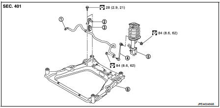
1. Stabilizer bar
2. Stabilizer clamp
3. Stabilizer bushing
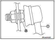
4. Stabilizer connecting rod
5. Strut assembly
6. Front suspension member
 : N·m (kg-m, ft-lb)
Removal and Installation
REMOVAL
1. Remove tires. Refer to WT-7, "Removal and Installation".
2. Remove front suspension member. Refer to FSU-18, "Removal and Installation".
3. Remove stabilizer connecting rod.
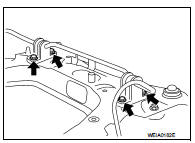
4. Remove mounting bolts ( ) of
) of
stabilizer clamp, and then
remove stabilizer clamp and stabilizer bushing from front suspension
member.
5. Remove stabilizer bar.
6. Perform inspection after removal. Refer to FSU-17, "Inspection".
INSTALLATION
Note the following, and install in the reverse order of removal.
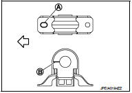
• Install stabilizer clamp and stabilizer bush with notch (A) and slit (B) faced forward of the vehicle ( ).
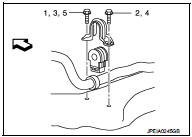
• To install stabilizer clamp mounting bolt, follow the tightening method and the numerical order shown below:
Manual tightening : 1 Temporary tightening : 2 → 3 Final tightening (Specified torque) : 4 → 5
 : Vehicle front
• To install stabilizer connecting rod (1), tighten the mounting nut with the hexagonal part (A) on the stabilizer connecting rod side fixed.
• Perform final tightening of bolts and nuts at the vehicle installation position (rubber bushing), under unladen conditions with tires on level ground.
• Perform inspection after installation. Refer to FSU-14, "Inspection".
Inspection
INSPECTION AFTER REMOVAL
Check stabilizer bar, stabilizer connecting rod, stabilizer bushing and stabilizer clamp for deformation, cracks or damage. Replace it if necessary.
INSPECTION AFTER INSTALLATION
Check wheel alignment. Refer to FSU-7, "Inspection".
 Transverse link
Exploded View
1. Front suspension member
2. Transverse link
: Always replace after every
disassembly.
: N·m (kg-m, ft-lb)
Removal and Installation
REMOVAL
1. Remove tires. Refer to WT-7, ...
 Front suspension member
Exploded View
2WD
1. Front suspension member
2. Damper assembly*
3. Rebound stopper rubber
4. Washer
5. Member stay
6. Rebound stopper
: N·m (kg-m, ft-lb)
*: For K9K models
4WD
1. ...
Other materials:
Additional service when replacing control unit
Description
When the control unit replaced, the initialization in necessary for normal
operation of power window system.
CAUTION:
The following specified operations can not be performed under the
non-initialized condition.
• Auto-up operation
• Anti-pinch function
Work Procedure
1.S ...
ACC warning does not operate
Diagnosis Procedure
1.CHECK COMBINATION METER BUZZER
Check combination meter buzzer.
Refer to WCS-40, "Component Function Check".
Is the inspection result normal?
YES >> GO TO 2.
NO >> Repair or replace the malfunctioning parts.
2.REPLACE BCM
1. Replace BCM. Ref ...
Diagnosis system (air bag)
Description
CAUTION:
• Never use electrical test equipment on any circuit related to the SRS unless
instructed in this Service
Manual. SRS wiring harnesses can be identified by yellow and/or orange harnesses
or harness
connectors.
• Never repair, splice or modify the SRS wiring harness. ...
