Nissan Juke Service and Repair Manual : Front suspension member
Exploded View
2WD
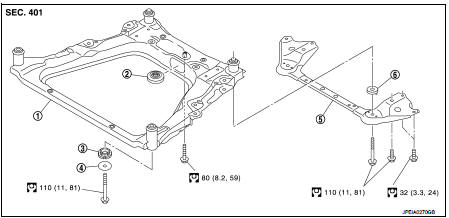
1. Front suspension member
2. Damper assembly*
3. Rebound stopper rubber
4. Washer
5. Member stay
6. Rebound stopper
 : N·m (kg-m, ft-lb)
*: For K9K models
4WD
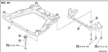
1. Front suspension member
2. Rebound stopper rubber
3. Washer
4. Member stay
5. Rebound stopper
: N·m (kg-m, ft-lb)
Removal and Installation
REMOVAL
1. Separate intermediate shaft from steering gear assembly. Refer to ST-14, "Removal and Installation".
2. Remove tires. Refer to WT-7, "Removal and Installation".
3. Remove front under cover.
4. Separate stabilizer connecting rod from strut assembly. Refer to FSU-16, "Removal and Installation".
5. Separate steering outer socket from steering knuckle. Refer to ST-19, "Removal and Installation".
6. Separate transverse link from steering knuckle.
• MR16DDT: Refer to FAX-11, "Removal and Installation".
• HR16DE: Refer to FAX-43, "Removal and Installation".
• K9K: Refer to FAX-68, "Removal and Installation".
7. Remove rear torque rod.
• MR16DDT: Refer to EM-55, "2WD : Removal and Installation".
• HR16DE: Refer to EM-215, "Removal and Installation".
• K9K: Refer to EM-326, "Removal and Installation".
8. Set suitable jack under front suspension member.
CAUTION:
Check the stable condition when using a jack.
9. Remove member stay and rebound stopper.
10. Remove suspension member mounting bolts, washer, and rebound stopper rubber.
11. Gradually lower the jack to remove front suspension member from vehicle body.
CAUTION:
Operate while checking that jack supporting status is stable.
NOTE:
Remove it with each component parts.
12. Remove damper assembly from front suspension member. (K9K models only) 13. Remove component parts from front suspension member.
14. Perform inspection after removal. Refer to FSU-14, "Inspection".
INSTALLATION
Note the following, and install in the reverse order of removal.
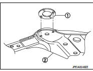
• To install rebound stopper (1), insert it with the protrusion aligned with the hole of member stay (2).
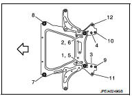
• To install member stay and mounting bolts of front suspension member, temporarily tighten the bolts before tightening to the specified torque, referring to the tightening method and the numerical order shown below:
Temporary tightening : 1 → 2 Final tightening (Specified torque) : 3 → 4 → 5 → 6 → 7 → 8 → 9 → 10 → 11 → 12
 : Vehicle front
• Perform final tightening of bolts and nuts at the vehicle installation position (rubber bushing), under unladen conditions with tires on level ground.
• Perform inspection after installation. Refer to FSU-14, "Inspection".
Inspection
INSPECTION AFTER REMOVAL
Check front suspension member for cracks, wear or damage. Replace it if necessary.
INSPECTION AFTER INSTALLATION
1. Check wheel sensor harness for proper connector.
2. Check wheel alignment. Refer to FSU-7, "Inspection".
 Front stabilizer
Exploded View
1. Stabilizer bar
2. Stabilizer clamp
3. Stabilizer bushing
4. Stabilizer connecting rod
5. Strut assembly
6. Front suspension member
: N·m (kg-m, ft-lb)
Removal and Insta ...

Other materials:
Accelerator pedal released position learning
Description
Accelerator Pedal Released Position Learning is a function of ECM to learn
the fully released position of the
accelerator pedal by monitoring the accelerator pedal position sensor output
signal. It must be performed each
time harness connector of accelerator pedal position sensor ...
Front passenger air bag module
Exploded View
1. Front passenger air bag module
2. Instrument panel assembly
: Pawl
: Do not reuse
: N·m (kg-m, ft-lb)
Removal and Installation
WARNING:
• Before servicing, turn ignition switch OFF, disconnect battery negative
terminal and wait 3 minutes
or more.
• Always work fr ...
Booster seats
For detailed guidance on safely installing a booster seat within your Nissan Leaf, please carefully follow the instructions and safety standards outlined in this section.
Precautions on booster seats
WARNING
Improper use of a booster seat or the vehicle's seat belt significantly incre ...
