Nissan Juke Service and Repair Manual : Radiator
Exploded View
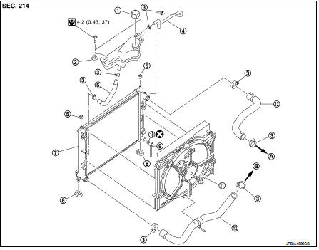
1. Reservoir tank cap
2. Reservoir tank
3. Clamp
4. Reservoir tank hose
5. Mounting rubber (upper)
6. Reservoir tank hose
7. Radiator
8. Mounting rubber (lower)
9. Drain plug
10. O-ring
11. Cooling fan assembly
12. Radiator hose (upper)
13. Radiator hose (lower)
A. To water outlet
B. To water inlet
 : N·m (kg-m, in-lb)
Removal and Installation
WARNING:
Never remove the reservoir tank cap when the engine is hot. Serious burns could
occur from high
pressure coolant escaping from the radiator. Wrap a thick cloth around the cap.
Slowly turn it a quarter
turn to allow built-up pressure to escape. Carefully remove the cap by turning
it all the way.
REMOVAL
1. Drain engine coolant. Refer to CO-62, "Draining".
CAUTION:
Perform when engine is cold
.
2. Remove cooling fan shroud assembly. Refer to CO-68, "Exploded View".
CAUTION:
Be careful not to damage or scratch the radiator core.
3. Remove the following parts.
• Front grille assembly: Refer to EXT-18, "Exploded View".
• Front bumper: Refer to EXT-12, "Exploded View".
• Front combination lamp assembly (RH and LH): Refer to EXL-91, "Exploded View".
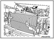
4. Remove radiator core support (upper).
5. Remove condenser fixing bolts upper.
6. Pull up and remove the radiator assembly (1).
2 : Condenser assembly
 : Vehicle front
CAUTION:
Be careful not to damage radiator core and condenser
assembly core.
INSTALLATION
• Reinstall any parts removed in reverse order of removal.
• Check for engine coolant leaks. Refer to CO-59, "Inspection".

 Cooling fan
Exploded View
1. Fan motorCooling fan
2. Fan shroud
3. Cooling fan
A. Reverse screw
: Apply thread locking sealant.
: Vehicle front
: N·m (kg-m, in-lb)
Removal and Installation
REMOVAL
...
Other materials:
B1081 seat belt Pre-tensioner RH
DTC Logic
DTC DETECTION LOGIC
DTC CONFIRMATION PROCEDURE
1.CHECK SELF-DIAG RESULT
With CONSULT-III
1. Turn ignition switch ON.
2. Perform “Self Diagnostic Result” mode of “AIR BAG” using CONSULT-III.
Without CONSULT-III
1. Turn ignition switch ON.
2. Check the air bag warning la ...
Front oil seal
FRONT OIL SEAL : Removal and Installation
REMOVAL
1. Remove the following parts.
• Front fender protector (RH): Refer to EXT-22, "Exploded View".
• Drive belt: Refer to EM-20, "Exploded View".
• Crankshaft pulley: Refer to EM-67, "Exploded View".
2. Remove ...
Can communication circuit
Diagnosis Procedure
1.CONNECTOR INSPECTION
1. Turn the ignition switch OFF.
2. Disconnect the battery cable from the negative terminal.
3. Disconnect all the unit connectors on CAN communication system.
4. Check terminals and connectors for damage, bend and loose connection.
Is the inspectio ...
