Nissan Juke Service and Repair Manual : Cooling fan
Exploded View
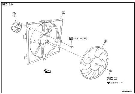
1. Fan motorCooling fan
2. Fan shroud
3. Cooling fan
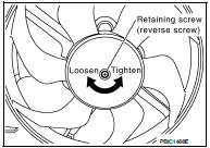
A. Reverse screw
 : Apply thread locking sealant.
 : Vehicle front
 : N·m (kg-m, in-lb)
Removal and Installation
REMOVAL
1. Drain engine coolant. Refer to CO-62, "Draining".
2. Disconnect radiator hose (lower) clip.
3. Remove battery. Refer to PG-124, "Exploded View" 4. Remove air duct (inlet). Refer to EM-280, "Exploded View".
5. Remove fusible link and relay box bracket, and put fusible link and relay box aside.
6. Remove reservoir tank.
7. Disconnect fan motor connector and boost pressure control valve harness connector, and put the connectors aside.
8. Remove boost pressure control valve assembly. Refer to EC-825, "TURBOCHARGER BOOST CONTROL : Vacuum Hose Drawing".
9. Remove radiator upper hose. Refer to CO-66, "Exploded View".
10. Remove radiator fan and shroud assembly.
11. Remove radiator fan reverse screw.
12. Remove fan motor from fan shroud.
INSTALLATION
Install in the reverse order of removal.
 Radiator
Exploded View
1. Reservoir tank cap
2. Reservoir tank
3. Clamp
4. Reservoir tank hose
5. Mounting rubber (upper)
6. Reservoir tank hose
7. Radiator
8. Mounting rubber (lower)
9. Drain ...
 Water pump
Exploded View
1. Water pump
2. Gasket
3. Cylinder block
Removal and Installation
WARNING:
Never remove the radiator cap when the engine is hot. Serious burns could occur
from high pressure ...
Other materials:
Daytime running light relay circuit
Component Function Check
1.CHECK DAYTIME RUNNING LIGHT OPERATION
CONSULT-III ACTIVE TEST
1. Select “EXTERNAL LAMPS” of IPDM E/R active test item.
2. With operating the test item, check that parking lamp, tail lamp and license
plate lamp are turned ON.
TAIL : Parking lamp, tail lamp and li ...
P0487 EGR volume control valve
DTC Logic
DTC DETECTION LOGIC
Diagnosis Procedure
1.CHECK EGR VOLUME CONTROL VALVE CONTROL CIRCUIT
1. Turn ignition switch OFF.
2. Disconnect EGR volume control valve harness connector and ECM harness
connector.
3. Check the continuity between EGR volume control valve terminal harness
co ...
Mainshaft and gear
Exploded View
1. Mainshaft front bearing outer
race
2. Mainshaft front bearing inner race
3. Mainshaft
4. 1st main gear
5. 1st inner baulk ring
6. 1st synchronizer cone
7. 1st outer baulk ring
8. 1st-2nd coupling sleeve
9. Insert key
10. 1st-2nd synchronizer hub
11. 2nd outer baulk ...
