
Nissan Juke Service and Repair Manual : B210A steering lock unit
DTC Logic
DTC DETECTION LOGIC

DTC CONFIRMATION PROCEDURE
1.PERFORM DTC CONFIRMATION PROCEDURE 1
1. Press push-button ignition switch under the following conditions and wait 1 second or more.
- Selector lever: In the P position - Brake pedal: Not depressed 2. Check DTC in “Self Diagnostic Result� mode of “IPDM E/R� using CONSULT-III.
Is DTC detected? YES >> Go to SEC-140, "Diagnosis Procedure".
NO >> GO TO 2.
2.PERFORM DTC CONFIRMATION PROCEDURE 2
1. Turn ignition switch ON.
2. Turn ignition switch OFF.
3. Press driver side door switch and wait 1 second or more.
4. CCheck DTC in “Self Diagnostic Result� mode of “IPDM E/R� using CONSULT-III.
Is DTC detected? YES >> Go to SEC-140, "Diagnosis Procedure".
NO >> INSPECTION END
Diagnosis Procedure
1.CHECK IPDM E/R INPUT SIGNAL
1. Turn ignition switch OFF.
2. Check voltage between IPDM E/R harness connector and ground.
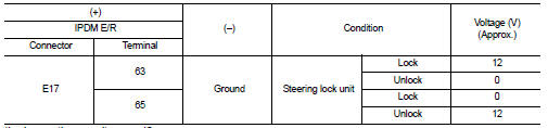
Is the inspection result normal? YES >> Replace IPDM E/R. Refer to PCS-34, "Removal and Installation".
NO >> GO TO 2.
2.CHECK IPDM E/R INPUT SIGNAL CIRCUIT
1. Disconnect IPDM E/R connector and steering lock unit connector.
2. Check continuity between IPDM E/R harness connector and steering lock unit harness connector.

3. Check continuity between IPDM E/R harness connector and ground.

Is the inspection result normal? YES >> GO TO 3.
NO >> Repair or replace harness.
3.REPLACE STEERING LOCK UNIT
1. Replace steering lock unit.
2. Perform the service procedure for steering lock unit replacement. Refer to CONSULT-III Operation Manual NATS-IVIS/NVIS.
>> INSPECTION END
 B2109 steering lock relay
DTC Logic
DTC DETECTION LOGIC
NOTE:
• If DTC B2109 is displayed with DTC U1000, first perform the trouble diagnosis
for DTC U1000. Refer to
PCS-30, "DTC Logic".
• When IPDM E/R po ...
 B210B starter control relay
DTC Logic
DTC DETECTION LOGIC
NOTE:
If DTC B210B is displayed with DTC U1000, first perform the trouble diagnosis
for DTC U1000. Refer to PCS-
30, "DTC Logic".
DTC CONFIRMATION PROC ...
Other materials:
Locking with key
The power door lock system allows you to lock or unlock all doors simultaneously.
• Turning the driver’s door key cylinder to the front of the vehicle1 will
lock all doors and the lift gate.
• Turning the driver’s door key cylinder once to the rear of the vehicle2 will unlock
t ...
Auto door lock operation does not operate
Diagnosis Procedure
1.CHECK “AUTO LOCK SET� SETTING WITH CONSULT-III
1. Select “MULTI REMOTE ENT� of “BCM� using CONSULT-III.
2. Select “AUTO LOCK SET� in “WORK SUPPORT� mode.
3. Check “AUTO LOCK SET� in “WORK SUPPORT�.
Refer to DLK-502, "MULTI REMOTE ENT : CO ...
B1052, B1057 driver air bag module
DTC Logic
DTC DETECTION LOGIC
DTC CONFIRMATION PROCEDURE
1.CHECK SELF-DIAG RESULT
With CONSULT-III
1. Turn ignition switch ON.
2. Perform “Self Diagnostic Result� mode of “AIR BAG� using CONSULT-III.
Without CONSULT-III
1. Turn ignition switch ON.
2. Check the air bag warning la ...
