Nissan Juke Service and Repair Manual : Water pump
Exploded View
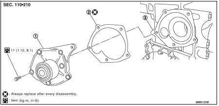
1. Water pump
2. Gasket
3. Cylinder block
Removal and Installation
WARNING:
Never remove the radiator cap when the engine is hot. Serious burns could occur
from high pressure
coolant escaping from the radiator.
REMOVAL
1. Drain engine coolant. Refer to CO-62, "Draining".
CAUTION:
Perform when engine is cold.
2. Remove front wheel RH.
3. Remove fender protector (RH). Refer to EXT-22, "Exploded View" 4. Remove drive belt. Refer to EM-276, "Removal and Installation".
5. Remove timing belt and inner cover. Refer to EM-302, "Exploded View".
6. Remove the water pump.
ŌĆó Coolant will leak from the cylinder block, so have a receptacle ready below.
CAUTION:
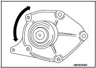
ŌĆó Handle the water pump vane so that it does not contact any other parts.
ŌĆó Water pump cannot be disassembled and should be replaced as a unit.
INSTALLATION
ŌĆó Install in the reverse order of removal.
Inspection
INSPECTION AFTER REMOVAL
ŌĆó Visually make sure there is no significant dirt or rusting on the water pump body and vane.
ŌĆó Make sure there is no looseness in the vane shaft, and that it turns smoothly when rotated by hand.
ŌĆó If there are any unusualness, replace the water pump assembly.
INSPECTION AFTER INSTALLATION
ŌĆó Check for engine coolant leaks using reservoir tank cap tester. Refer to CO-62, "Inspection".
 Cooling fan
Exploded View
1. Fan motorCooling fan
2. Fan shroud
3. Cooling fan
A. Reverse screw
: Apply thread locking sealant.
: Vehicle front
: N┬Ęm (kg-m, in-lb)
Removal and Installation
REMOVAL
...
 Thermo plunger unit
Exploded View
1. Side member LH
2. Thermo plunger control unit
3. Thermo plunger relay
4. Thermo plunger connector
5. Earth lead
6. Thermo plunger unit
7. Bracket stay
Vehicle front
: ...
Other materials:
B26F4 starter control relay
DTC Logic
DTC DETECTION LOGIC
NOTE:
ŌĆó If DTC B26F4 is displayed with DTC U1000, first perform the trouble diagnosis
for DTC U1000. Refer to
BCS-83, "DTC Logic".
ŌĆó If DTC B26F4 is displayed with DTC U1010, first perform the trouble diagnosis
for DTC U1010. Refer to
BCS-84, &qu ...
Precautions For Refrigerant System Service
GENERAL REFRIGERANT PRECAUTION
WARNING:
ŌĆó Never breathe A/C refrigerant and lubricant vapor or mist. Exposure may
irritate eyes, nose and
throat. Use only approved recovery/recycling equipment to discharge HFC-134a
(R-134a) refrigerant.
Ventilate work area before resuming service if acci ...
Compressor dose dot operate
Description
SYMPTOM
Compressor dose not operate.
Diagnosis Procedure
NOTE:
ŌĆó Perform self-diagnosis with CONSULT-III before performing symptom diagnosis.
If any malfunction result or
DTC is detected, perform the corresponding diagnosis.
ŌĆó Check that refrigerant is enclosed in cooler cyc ...
