Nissan Juke Service and Repair Manual : Door lock actuator
Driver side
DRIVER SIDE : Component Function Check
1.CHECK FUNCTION
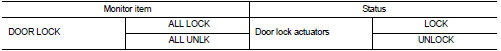
1. Select ÔÇťDOOR LOCKÔÇŁ of ÔÇťBCMÔÇŁ using CONSULT-III.
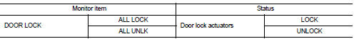
2. Select ÔÇťDOOR LOCKÔÇŁ in ÔÇťACTIVE TESTÔÇŁ mode.
3. Check that the function operates normally according to the following conditions.
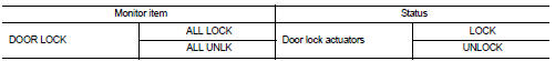
Is the inspection result normal? YES >> Door lock actuator is OK.
NO >> Refer to DLK-386, "DRIVER SIDE : Diagnosis Procedure".
DRIVER SIDE : Diagnosis Procedure
1.CHECK DOOR LOCK ACTUATOR INPUT SIGNAL
1. Turn ignition switch OFF.
2. Disconnect front door lock assembly (driver side) connector.
3. Check voltage between front door lock assembly (driver side) harness connector and ground.
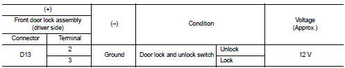
Is the inspection result normal? YES >> Replace front door lock assembly (driver side).
NO >> GO TO 2.
2.CHECK DOOR LOCK ACTUATOR CIRCUIT
1. Disconnect BCM connector and all door lock assembly connector.
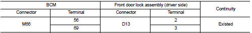
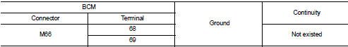
2. Check continuity between BCM harness connector and front door lock assembly (driver side) harness connector
3. Check continuity between BCM harness connector and ground.
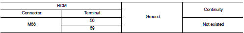
Is the inspection result normal? YES >> GO TO 3.
NO >> Repair or replace harness.
3.CHECK BCM OUTPUT SIGNAL
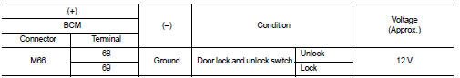
1. Connect BCM connector.
2. Check voltage between BCM harness connector and ground.
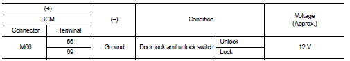
Is the inspection result normal? YES >> Check for internal short of each door lock actuator.
NO >> Replace BCM. Refer to BCS-161, "Removal and Installation".
Passenger side
PASSENGER SIDE : Component Function Check
1.CHECK FUNCTION
1. Select ÔÇťDOOR LOCKÔÇŁ of ÔÇťBCMÔÇŁ using CONSULT-III.
2. Select ÔÇťDOOR LOCKÔÇŁ in ÔÇťACTIVE TESTÔÇŁ mode.
3. Check that the function operates normally according to the following conditions.
Is the inspection result normal? YES >> Door lock actuator is OK.
NO >> Refer to DLK-386, "DRIVER SIDE : Diagnosis Procedure".
PASSENGER SIDE : Diagnosis Procedure
1.CHECK DOOR LOCK ACTUATOR INPUT SIGNAL
1. Turn ignition switch OFF.
2. Disconnect front door lock assembly (passenger side) connector.
3. Check voltage between front door lock assembly (passenger side) harness connector and ground.
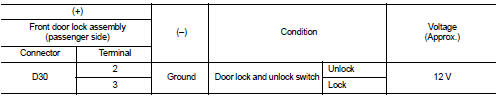
Is the inspection result normal? YES >> Replace front door lock assembly (passenger side).
NO >> GO TO 2.
2.CHECK DOOR LOCK ACTUATOR CIRCUIT
1. Disconnect BCM connector and all door lock assembly connector.
2. Check continuity between BCM harness connector and front door lock assembly (passenger side) harness connector.
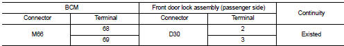
3. Check continuity between BCM harness connector and ground.
Is the inspection result normal? YES >> GO TO 3.
NO >> Repair or replace harness.
3.CHECK BCM OUTPUT SIGNAL
1. Connect BCM connector.
2. Check voltage between BCM harness connector and ground.
Is the inspection result normal? YES >> Check for internal short of each door lock actuator.
NO >> Replace BCM. Refer to BCS-161, "Removal and Installation".
Rear LH
REAR LH : Component Function Check
1.CHECK FUNCTION
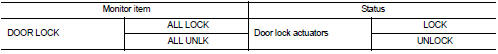
1. Select ÔÇťDOOR LOCKÔÇŁ of ÔÇťBCMÔÇŁ using CONSULT-III.
2. Select ÔÇťDOOR LOCKÔÇŁ in ÔÇťACTIVE TESTÔÇŁ mode.
3. Check that the function operates normally according to the following conditions.
Is the inspection result normal? YES >> Door lock actuator is OK.
NO >> Refer to DLK-386, "DRIVER SIDE : Diagnosis Procedure".
REAR LH : Diagnosis Procedure
1.CHECK DOOR LOCK ACTUATOR INPUT SIGNAL
1. Turn ignition switch OFF.
2. Disconnect rear door lock assembly LH connector.
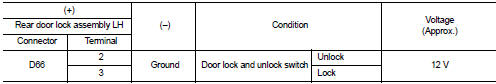
3. Check voltage between rear door lock assembly LH harness connector and ground.
Is the inspection result normal? YES >> Replace rear door lock assembly LH.
NO >> GO TO 2.
2.CHECK DOOR LOCK ACTUATOR CIRCUIT
1. Disconnect BCM connector and all door lock assembly connector.
2. Check continuity between BCM harness connector and rear door lock assembly LH harness connecto
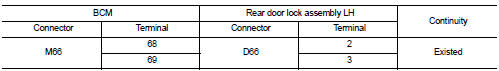
3. Check continuity between BCM harness connector and ground.
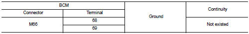
Is the inspection result normal? YES >> GO TO 3.
NO >> Repair or replace harness.
3.CHECK BCM OUTPUT SIGNAL
1. Connect BCM connector.
2. Check voltage between BCM harness connector and ground.
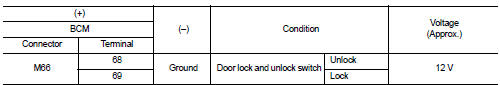
Is the inspection result normal? YES >> Check for internal short of each door lock actuator.
NO >> Replace BCM. Refer to BCS-161, "Removal and Installation".
Rear RH
REAR RH : Component Function Check
1.CHECK FUNCTION
1. Select ÔÇťDOOR LOCKÔÇŁ of ÔÇťBCMÔÇŁ using CONSULT-III.
2. Select ÔÇťDOOR LOCKÔÇŁ in ÔÇťACTIVE TESTÔÇŁ mode.
3. Check that the function operates normally according to the following conditions.
Is the inspection result normal? YES >> Door lock actuator is OK.
NO >> Refer to DLK-386, "DRIVER SIDE : Diagnosis Procedure".
REAR RH : Diagnosis Procedure
1.CHECK DOOR LOCK ACTUATOR INPUT SIGNAL
1. Turn ignition switch OFF.
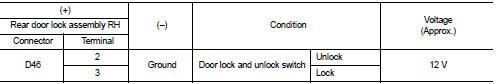
2. Disconnect rear door lock assembly RH connector.
3. Check voltage between rear door lock assembly RH harness connector and ground.
Is the inspection result normal? YES >> Replace rear door lock assembly RH.
NO >> GO TO 2.
2.CHECK DOOR LOCK ACTUATOR CIRCUIT
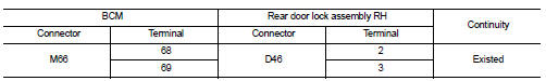
1. Disconnect BCM connector and all door lock assembly connector.
2. Check continuity between BCM harness connector and rear door lock assembly RH harness connector.
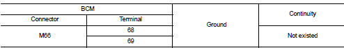
3. Check continuity between BCM harness connector and ground.
Is the inspection result normal? YES >> GO TO 3.
NO >> Repair or replace harness.
3.CHECK BCM OUTPUT SIGNAL
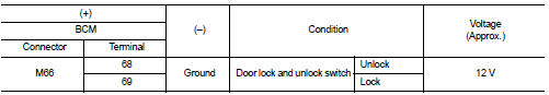
1. Connect BCM connector.
2. Check voltage between BCM harness connector and ground.
Is the inspection result normal? YES >> Check for internal short of each door lock actuator.
NO >> Replace BCM. Refer to BCS-161, "Removal and Installation".
 Back door opener switch
Component Function Check
1.CHECK FUNCTION
1. Select ÔÇťTRUNKÔÇŁ of ÔÇťBCMÔÇŁ using CONSULT-III.
2. Select ÔÇťTRNK OPNR SWÔÇŁ in ÔÇťDATA MONITORÔÇŁ mode.
3. Check that the function operates normall ...
 Door lock and unlock switch
Driver side
DRIVER SIDE : Component Function Check
1.CHECK FUNCTION
1. Select ÔÇťDOOR LOCKÔÇŁ of ÔÇťBCMÔÇŁ using CONSULT-III.
2. Select ÔÇťCDL LOCK SWÔÇŁ, ÔÇťCDL UNLOCK SWÔÇŁ in ÔÇťDATA MONITORÔÇŁ ...
Other materials:
B2623 inside antenna
DTC Logic
DTC DETECTION LOGIC
DTC CONFIRMATION PROCEDURE
1.PERFORM DTC CONFIRMATION PROCEDURE
1. Select ÔÇťINTELLIGENT KEYÔÇŁ of ÔÇťBCMÔÇŁ using CONSULT-III.
2. Select ÔÇťINSIDE ANT DIAGNOSISÔÇŁ in ÔÇťWORK SUPPORTÔÇŁ mode.
3. Perform inside key antenna (ÔÇťINSIDE ANT DIAGNOSISÔÇŁ) on ÔÇťWORK ...
Drive belt
Checking Drive Belts
WARNING:
Be sure to perform when the engine is stopped.
1. Inspect belts for cracks, fraying, wear and oil. If necessary,
replace.
2. Evaluate manually if the belt is enough tensioned (tension cannot
be measured by way of frequency meter).
CAUTION:
Auto-tensioner must ...
Transverse link
Exploded View
1. Front suspension member
2. Transverse link
: Always replace after every
disassembly.
: N┬Ěm (kg-m, ft-lb)
Removal and Installation
REMOVAL
1. Remove tires. Refer to WT-7, "Removal and Installation".
2. Remove transverse link from steering knuckle.
ÔÇó MR16D ...
