Nissan Juke Service and Repair Manual : Door lock and unlock switch
Driver side
DRIVER SIDE : Component Function Check
1.CHECK FUNCTION
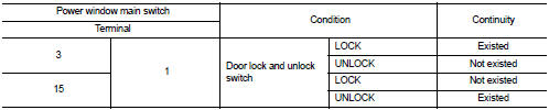
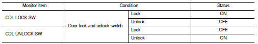
1. Select ÔÇťDOOR LOCKÔÇŁ of ÔÇťBCMÔÇŁ using CONSULT-III.
2. Select ÔÇťCDL LOCK SWÔÇŁ, ÔÇťCDL UNLOCK SWÔÇŁ in ÔÇťDATA MONITORÔÇŁ mode.
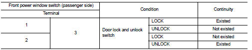
3. Check that the function operates normally according to the following conditions.
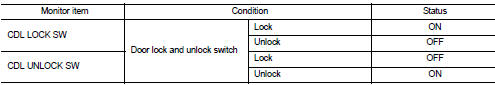
Is the inspection result normal? YES >> Door lock and unlock switch is OK.
NO >> Refer to DLK-391, "DRIVER SIDE : Diagnosis Procedure".
DRIVER SIDE : Diagnosis Procedure
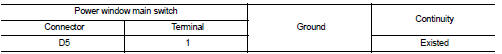
1.CHECK DOOR LOCK AND UNLOCK SWITCH INPUT SIGNAL
1. Turn ignition switch OFF.
2. Disconnect power window main switch connector.
3. Check signal between power window main switch harness connector and ground using oscilloscope.
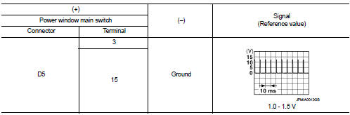
Is the inspection result normal? YES >> GO TO 3.
NO >> GO TO 2.
2.CHECK DOOR LOCK AND UNLOCK SWITCH CIRCUIT
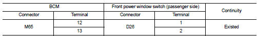
1. Disconnect BCM connector and front power window switch (passenger side) connector.
2. Check continuity between BCM harness connector and power window main switch harness connector.
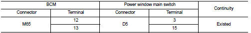
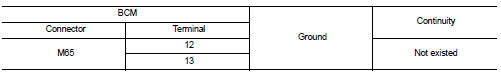
3. Check continuity between BCM harness connector and ground.
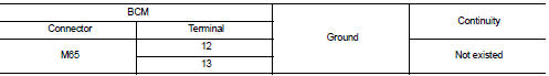
Is the inspection result normal? YES >> Replace BCM. Refer to BCS-93, "Removal and Installation".
NO >> Repair or replace harness.
3.CHECK DOOR LOCK AND UNLOCK SWITCH GROUND
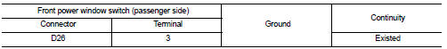
Check continuity between power window main switch harness connector and ground.
Is the inspection result normal? YES >> GO TO 4.
NO >> Repair or replace harness.
4.CHECK DOOR LOCK AND UNLOCK SWITCH
Refer to DLK-392, "DRIVER SIDE : Component Inspection".
Is the inspection result normal? YES >> GO TO 5.
NO >> Replace power window main switch. Refer to PWC-44, "Removal and Installation".
5.CHECK INTERMITTENT INCIDENT
Refer to GI-42, "Intermittent Incident".
>> INSPECTION END
DRIVER SIDE : Component Inspection
1.CHECK DOOR LOCK AND UNLOCK SWITCH
1. Turn ignition switch OFF.
2. Disconnect power window main switch connector.
3. Check continuity between power window main switch terminals.
Is the inspection result normal? YES >> INSPECTION END
NO >> Replace power window main switch.
Passenger side
PASSENGER SIDE : Component Function Check
1.CHECK FUNCTION
1. Select ÔÇťDOOR LOCKÔÇŁ of ÔÇťBCMÔÇŁ using CONSULT-III.
2. Select ÔÇťCDL LOCK SWÔÇŁ, ÔÇťCDL UNLOCK SWÔÇŁ in ÔÇťDATA MONITORÔÇŁ mode.
3. Check that the function operates normally according to the following conditions.
Is the inspection result normal? YES >> Door lock and unlock switch is OK.
NO >> Refer to DLK-393, "PASSENGER SIDE : Diagnosis Procedure".
PASSENGER SIDE : Diagnosis Procedure
1.CHECK DOOR LOCK AND UNLOCK SWITCH INPUT SIGNAL
1. Turn ignition switch OFF.
2. Disconnect front power window switch (passenger side) connector.
3. Check signal between front power window switch (passenger side) harness connector and ground using oscilloscope.
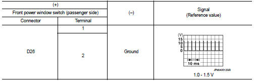
Is the inspection result normal? YES >> GO TO 3.
NO >> GO TO 2.
2.CHECK DOOR LOCK AND UNLOCK SWITCH CIRCUIT
1. Disconnect BCM connector and power window main switch connector.
2. Check continuity between BCM harness connector and front power window switch (passenger side) harness connector.
3. Check continuity between BCM harness connector and ground.
Is the inspection result normal? YES >> Replace BCM. Refer to BCS-161, "Removal and Installation".
NO >> Repair or replace harness.
3.CHECK DOOR LOCK AND UNLOCK SWITCH GROUND
Check continuity between front power window switch (passenger side) harness connector and ground.
Is the inspection result normal? YES >> GO TO 4.
NO >> Repair or replace harness.
4.CHECK DOOR LOCK AND UNLOCK SWITCH
Refer to DLK-394, "PASSENGER SIDE : Component Inspection".
Is the inspection result normal? YES >> GO TO 5.
NO >> Replace front power window switch (passenger side). Refer to PWC-44, "Removal and Installation".
5.CHECK INTERMITTENT INCIDENT
Refer to GI-42, "Intermittent Incident".
>> INSPECTION END
Passenger side : Component Inspection
1.CHECK DOOR LOCK AND UNLOCK SWITCH
1. Turn ignition switch OFF.
2. Disconnect front power window switch (passenger side) connector.
3. Check continuity between front power window switch (passenger side) terminals.
Is the inspection result normal? YES >> INSPECTION END
NO >> Replace front power window switch (passenger side).
 Door lock actuator
Driver side
DRIVER SIDE : Component Function Check
1.CHECK FUNCTION
1. Select ÔÇťDOOR LOCKÔÇŁ of ÔÇťBCMÔÇŁ using CONSULT-III.
2. Select ÔÇťDOOR LOCKÔÇŁ in ÔÇťACTIVE TESTÔÇŁ mode.
3. Check that th ...
 Door lock status indicator
Component Function Check
1.CHECK FUNCTION
1. Select ÔÇťDOOR LOCKÔÇŁ of ÔÇťBCMÔÇŁ using CONSULT-III.
2. Select ÔÇťDOOR LOCK INDÔÇŁ in ÔÇťACTIVE TESTÔÇŁ mode.
3. Check that the function operates nor ...
Other materials:
Inside mirror
Adjust the angle of the inside mirror to the desired position.
The night position1 will reduce glare from the headlights of vehicles behind
you at night.
Use the day position2 when driving in daylight hours.
WARNING
Use the night position only when necessary, because it reduces rear view c ...
P1701 TCM
Description
When the power supply to the TCM is cut OFF, for example because the battery
is removed, and the self-diagnosis
memory function stops, malfunction is detected.
NOTE:
Since ÔÇťP1701ÔÇŁ will be indicated when replacing TCM, perform diagnosis after
erasing ÔÇťSELF-DIAG
RESULTSÔÇŁ ...
P2135 TP sensor
DTC Logic
DTC DETECTION LOGIC
NOTE:
If DTC P2135 is displayed with DTC P0643, first perform the trouble diagnosis
for DTC P0643. Refer to
EC-307, "DTC Logic".
DTC CONFIRMATION PROCEDURE
1.PRECONDITIONING
If DTC Confirmation Procedure has been previously conducted, always perform ...
