Nissan Juke Service and Repair Manual : Speed limiter main switch
Component Function Check
1.CHECK SPEED LIMITER MAIN SWITCH FUNCTION
 With CONSULT-III
1. Turn ignition switch ON.
2. Select “ENGINE” using CONSULT-III.
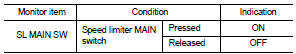
3. Select “SL MAIN SW” in “DATA MONITOR” mode.
4. Check “SL MAIN SW” indication under the following condition.
 Without CONSULT-III
1. Turn ignition switch ON.
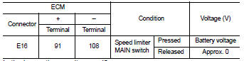
2. Check the voltage between ECM harness connector and ground under the following conditions.
Is the inspection result normal? YES >> INSPECTION END
NO >> Go to EC-792, "Diagnosis Procedure".
Diagnosis Procedure
1.CHECK GROUND CONNECTION
1. Turn ignition switch OFF.
2. Check ground connection E21 and E38. Refer to Ground Inspection in GI-44, "Circuit Inspection".
Is the inspection result normal? YES >> GO TO 2.
NO >> Repair or replace ground connection.
2.CHECK SPEED LIMITER MAIN SWITCH POWER SUPPLY CIRCUIT
1. Turn ignition switch OFF.
2. Disconnect combination switch (spiral cable) harness connector.
3. Turn ignition switch ON.
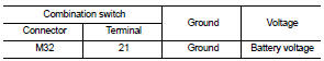
4. Check the voltage between combination switch harness connector and ground.
5. Also check harness for short to ground and short to power.
Is the inspection result normal? YES >> GO TO 4.
NO >> GO TO 3.
3.DETECT MALFUNCTIONING PART
Check the following.
• 10 A fuse (No. 3)
• Combination switch (spiral cable)
• Harness for open and short between combination switch and fuse
>> Repair open circuit, short to ground or short to power in harness or connectors.
4.CHECK SPEED LIMITER MAIN SWITCH INPUT SIGNAL CIRCUIT FOR OPEN AND SHORT
1. Disconnect ECM harness connector.
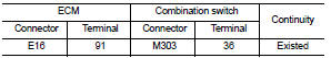
2. Check the continuity between ECM harness connector and combination switch harness connector.
3. Also check harness for short to ground and short to power.
Is the inspection result normal? YES >> GO TO 6.
NO >> GO TO 5.
5.DETECT MALFUNCTIONING PART
Check the following.
• Harness connectors E105, M77 • Combination switch (spiral cable) • Harness for open and short between ECM and combination switch
>> Repair open circuit, short to ground or short to power in harness or connectors.
6.CHECK STEERING SWITCH
Refer to EC-769, "Component Inspection (ASCD STEERING SWITCH)".
Is the inspection result normal? YES >> GO TO 7.
NO >> Replace ASCD steering switch.
7.CHECK INTERMITTENT INCIDENT
Refer to GI-42, "Intermittent Incident".
Is the inspection result normal? YES >> Replace IPDM E/R.
NO >> Repair open circuit, short to ground or short to power in harness or connectors.
Component Inspection (ASCD STEERING SWITCH)
1.CHECK ASCD STEERING SWITCH-I
1. Turn ignition switch OFF.
2. Disconnect combination switch (spiral cable) harness connector.
3. Check the continuity between combination switch harness connector terminals under the following condition.
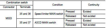
Is the inspection result normal? YES >> GO TO 2.
NO >> Replace ASCD steering switch.
2.CHECK ASCD STEERING SWITCH-II
Check resistance between combination switch (spiral cable) harness connector terminals under the following conditions.
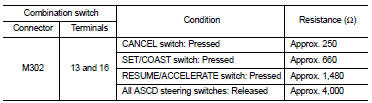
Is the inspection result normal? YES >> INSPECTION END
NO >> Replace ASCD steering switch.
 Refrigerant pressure sensor
Component Function Check
1.CHECK REFRIGERANT PRESSURE SENSOR OVERALL FUNCTION
1. Start engine and warm it up to normal operating temperature.
2. Turn A/C switch and blower fan switch ON.
3. Check ...

Other materials:
Precautions on cruise control
• If the cruise control system malfunctions, it will cancel automatically.
The CRUISE indicator light on the meter panel will then blink to warn the driver.
• If the engine coolant temperature becomes excessively high, the cruise control
system will cancel automatically.
•&nb ...
Precaution
Precaution for Supplemental Restraint System (SRS) "AIR BAG" and "SEAT BELT
PRE-TENSIONER"
The Supplemental Restraint System such as “AIR BAG” and “SEAT BELT PRE-TENSIONER”,
used along
with a front seat belt, helps to reduce the risk or severity of injury to the
dr ...
Explanation of scheduled maintenance items
The following detailed descriptions are designed to provide you with a comprehensive understanding of the scheduled maintenance items that require periodic inspection or replacement to keep your Nissan Leaf running at its peak. Your official maintenance schedule serves as a roadmap, explicitly indic ...
