Nissan Juke Service and Repair Manual : Door lock status indicator
Component Function Check
1.CHECK FUNCTION
1. Select “DOOR LOCK” of “BCM” using CONSULT-III.
2. Select “DOOR LOCK IND” in “ACTIVE TEST” mode.
3. Check that the function operates normally according to the following conditions.
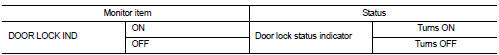
Is the inspection result normal? YES >> Door lock status indicator is OK.
NO >> Refer to DLK-395, "Diagnosis Procedure".
Diagnosis Procedure
1.CHECK DOOR LOCK STATUS INDICATOR INPUT SIGNAL
1. Turn ignition switch OFF.
2. Disconnect door lock status indicator connector.
3. Check voltage between door lock status indicator harness connector and ground.
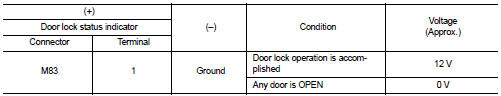
Is the inspection result normal? YES >> GO TO 3.
NO >> GO TO 2.
2.CHECK DOOR LOCK STATUS INDICATOR CIRCUIT
1. Disconnect BCM connector.
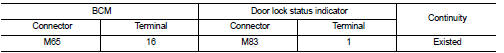
2. Check continuity between BCM harness connector and door lock status indicator harness connector.
3. Check continuity between BCM harness connector and ground.
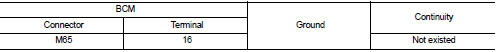
Is the inspection result normal? YES >> Replace BCM. Refer to BCS-161, "Removal and Installation".
NO >> Repair or replace harness.
3.CHECK DOOR LOCK STATUS INDICATOR GROUND
Check continuity between door lock status indicator harness connector and ground.
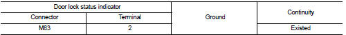
Is the inspection result normal? YES >> Replace door lock status indicator.
NO >> Repair or replace harness.
 Door lock and unlock switch
Driver side
DRIVER SIDE : Component Function Check
1.CHECK FUNCTION
1. Select “DOOR LOCK” of “BCM” using CONSULT-III.
2. Select “CDL LOCK SW”, “CDL UNLOCK SW” in “DATA MONITOR” ...
 Door switch
Component Function Check
1.CHECK FUNCTION
1. Select “DOOR LOCK” of “BCM” using CONSULT-III.
2. Select “DOOR SW-DR”, “DOOR SW-AS”, “DOOR SW-RL”, “DOOR SW-RR”, “BACK DOOR SW ...
Other materials:
Basic inspection
DIAGNOSIS AND REPAIR WORK FLOW
Work Flow
DETAILED FLOW
1.OBTAIN INFORMATION ABOUT SYMPTOM
Interview the customer to obtain the malfunction information (conditions and
environment when the malfunction
occurred) as much as possible when the customer brings the vehicle in.
>> GO TO 2.
...
Control linkage
Exploded View
1. Bracket
2. Selector cable
3. Shifter lever A
4. Selector lever
5. Cable mounting bracket
6. Tapping bolt
7. Shifter cable
8. Grommet
9. M/T shift selector assembly
10. Shifter lever
11. Shifter lever knob
: Always replace after every
disassembly.
: N·m (kg-m ...
Symptom diagnosis
Squeak and rattle trouble diagnoses
Work Flow
CUSTOMER INTERVIEW
Interview the customer if possible, to determine the conditions that exist
when the noise occurs. Use the Diagnostic
Worksheet during the interview to document the facts and conditions when the
noise occurs and any of
the cu ...
