Nissan Juke Service and Repair Manual : Back door opener switch
Component Function Check
1.CHECK FUNCTION
1. Select “TRUNK” of “BCM” using CONSULT-III.
2. Select “TRNK OPNR SW” in “DATA MONITOR” mode.
3. Check that the function operates normally according to the following conditions.
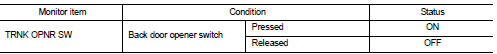
Is the inspection result normal? YES >> Back door opener switch is OK.
NO >> Refer to DLK-384, "Diagnosis Procedure".
Diagnosis Procedure
1.CHECK BACK DOOR OPEN INPUT SIGNAL
1. Turn ignition switch OFF.
2. Disconnect back door opener switch connector.
3. Check signal between back door opener switch harness connector and ground using oscilloscope.
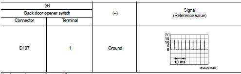
Is the inspection result normal? YES >> GO TO 3.
NO >> GO TO 2.
2.CHECK BACK DOOR OPENER SWITCH CIRCUIT
1. Disconnect BCM connector.
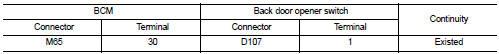
2. Check continuity between BCM harness connector and back door opener switch harness connector.
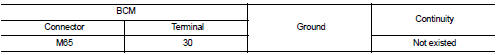
3. Check continuity between BCM harness connector and ground.
Is the inspection result normal? YES >> Replace BCM. Refer to BCS-161, "Removal and Installation".
NO >> Repair or replace harness.
3.CHECK BACK DOOR OPENER SWITCH GROUND CIRCUIT
Check continuity between back door opener switch harness connector and ground.
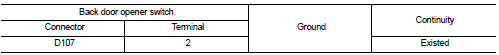
Is the inspection result normal? YES >> GO TO 4.
NO >> Repair or replace harness.
4.CHECK BACK DOOR OPENER SWITCH
Refer to DLK-385, "Component Inspection".
Is the inspection result normal? YES >> GO TO 5.
NO >> Replace back door opener switch.
5.CHECK INTERMITTENT INCIDENT
Refer to GI-42, "Intermittent Incident".
>> INSPECTION END
Component Inspection
1.CHECK BACK DOOR OPENER SWITCH
1. Turn ignition switch OFF.
2. Disconnect back door opener switch connector.
3. Check continuity between back door opener switch terminals.
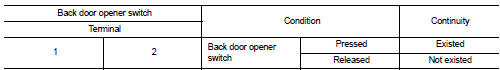
Is the inspection result normal? YES >> INSPECTION END
NO >> Replace back door opener switch.
 Back door opener actuator
Diagnosis Procedure
1.CHECK BACK DOOR OPENER ACTUATOR INPUT SIGNAL
1. Turn ignition switch OFF.
2. Disconnect back door opener assembly connector.
3. Check voltage between back door opener assembl ...
 Door lock actuator
Driver side
DRIVER SIDE : Component Function Check
1.CHECK FUNCTION
1. Select “DOOR LOCK” of “BCM” using CONSULT-III.
2. Select “DOOR LOCK” in “ACTIVE TEST” mode.
3. Check that th ...
Other materials:
Shift lock system
Component Function Check
1.CHECK SHIFT LOCK OPERATION (PART 1)
1. Turn ignition switch ON.
2. Shift the selector lever to “P” position.
3. Attempt to shift the selector lever to any other than position with the brake
pedal released.
Can the selector lever be shifted to any other positio ...
Car phone or CB radio
When installing a two-way CB, ham radio, or a dedicated car phone system in your Nissan Leaf, be sure to strictly observe the following technical precautions; otherwise, the newly integrated radio frequency equipment may adversely affect the sophisticated EV control system networks and other sensiti ...
Exterior and interior lights
: See a NISSAN dealer for replacement.
NOTE: Always check with the Parts Department at a NISSAN dealer for the latest
information about parts.
: REMOVE
: INSTALL
Replacement procedures
All other lights are either type A, B, C, D or E.
When replacing a bulb, first remove the lens and/or c ...
