Nissan Juke Service and Repair Manual : Shift lock system
Component Function Check
1.CHECK SHIFT LOCK OPERATION (PART 1)
1. Turn ignition switch ON.
2. Shift the selector lever to “P” position.
3. Attempt to shift the selector lever to any other than position with the brake pedal released.
Can the selector lever be shifted to any other position? YES >> Go to TM-471, "Diagnosis Procedure".
NO >> GO TO 2.
2.CHECK SHIFT LOCK OPERATION (PART 2)
Attempt to shift the selector lever to any other than position with the brake pedal depressed.
Can the selector lever be shifted to any other position? YES >> INSPECTION END
NO >> Go to TM-471, "Diagnosis Procedure".
Diagnosis Procedure
1.CHECK POWER SOURCE (PART 1)
1. Turn ignition switch OFF.
2. Disconnect stop lamp switch connector 3. Turn ignition switch ON.
4. Check the voltage between the stop lamp switch harness connector terminal and ground.
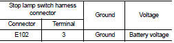
Is the inspection result normal? YES >> GO TO 2.
NO >> GO TO 9.
2.CHECK STOP LAMP SWITCH (PART 1)
Check stop lamp switch. Refer to TM-474, "Component Inspection (Stop Lamp Switch)".
Is the inspection result normal? YES >> GO TO 3.
NO >> GO TO 10.
3.CHECK CIRCUIT BETWEEN STOP LAMP SWITCH AND CVT SHIFT SELECTOR (PART 1)
1. Disconnect CVT shift selector connector 2. Check the continuity between the stop lamp switch harness connector terminal and the CVT shift selector harness connector terminal.
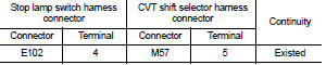
Is the inspection result normal? YES >> GO TO 4.
NO >> Repair or replace the malfunctioning parts.
4.CHECK CIRCUIT BETWEEN STOP LAMP SWITCH AND CVT SHIFT SELECTOR (PART 1)
Check the continuity between the stop lamp switch harness connector terminal and ground.
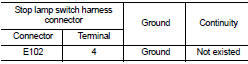
Is the inspection result normal? YES >> GO TO 5.
NO >> Repair or replace the malfunctioning parts.
5.CHCK GROUND CIRCUIT
Check the continuity between the CVT shift selector harness connector terminal and ground.
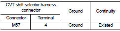
Is the inspection result normal? YES >> GO TO 6.
NO >> Repair or replace the malfunctioning parts.
6.CHECK PART POSITION SWITCH
1. Disconnect park position switch connector.
2. Check park position switch. Refer to TM-473, "Component Inspection (Park Position Switch)".
Is the inspection result normal? YES >> GO TO 7.
NO >> Repair or replace the malfunctioning parts.
7.CHECK SHIFT LOCK SOLENOID
1. Disconnect shift lock solenoid connector.
2. Check shift lock solenoid. Refer to TM-473, "Component Inspection (Shift Lock Solenoid)".
Is the inspection result normal? YES >> GO TO 8.
NO >> Repair or replace the malfunctioning parts.
8.CHECK CVT SHIFT SELECTOR HARNESS
Check CVT shift selector harness. Refer to TM-473, "Component Inspection (CVT Shift Selector Harness)".
Is the inspection result normal? YES >> Check intermittent incident. Refer to GI-42, "Intermittent Incident".
NO >> Repair or replace the malfunctioning parts.
9.DETECT MALFUNCTIONING ITEM
Check the following items: • Open or short circuit of the harness between ignition switch and stop lamp switch connector. Refer to PG-15, "Wiring Diagram - IGNITION POWER SUPPLY -".
• Ignition switch
• 10A fuse [No.3, fuse block (J/B)]. Refer to PG-22, "Fuse, Connector and
Terminal Arrangement".
Is the inspection result normal? YES >> Check intermittent incident. Refer to GI-42, "Intermittent Incident".
NO >> Repair or replace the malfunctioning parts.
10.CHECK INSTALLATION POSITION OF STOP LAMP SWITCH
Adjust stop lamp switch position. Refer to BR-9, "Inspection and Adjustment" (LHD) or BR-77, "Inspection and Adjustment" (RHD).
>> GO TO 11.
11.CHECK STOP LAMP SWITCH (PART 2)
Check stop lamp switch. Refer to TM-474, "Component Inspection (Stop Lamp Switch)".
Is the inspection result normal? YES >> INSPECTION END
NO >> Repair or replace the malfunctioning parts.
Component Inspection (Shift Lock Solenoid)
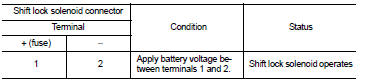
1.CHECK SHIFT LOCK SOLENOID
Apply voltage to terminals of shift lock solenoid connector and check that shift lock solenoid is activated.
CAUTION:
• Connect the fuse between the terminals when applying the voltage.
• Never cause shorting between terminals.
Is the inspection result normal? YES >> INSPECTION END
NO >> Replace the shift lock unit. Refer to TM-482, "Disassembly and Assembly".
Component Inspection (Park Position Switch)
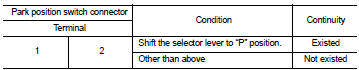
1.CHECK PARK POSITION SWITCH
Check the continuity between park position switch connector terminals.
CAUTION:
• Connect the fuse between the terminals when applying the voltage.
• Never cause shorting between terminals.
Is the inspection result normal? YES >> INSPECTION END
NO >> Replace the park position switch. Refer to TM-482, "Disassembly and Assembly".
Component Inspection (CVT Shift Selector Harness)
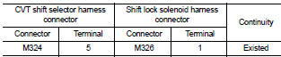
1.CHECK CVT SHIFT SELECTOR HARNESS (PART 1)
Check the continuity between the CVT shift selector harness connector terminal and the shift lock solenoid harness connector terminal.
Is the inspection result normal? YES >> GO TO 2.
NO >> Replace the CVT shift selector harness. Refer to TM-482, "Disassembly and Assembly".
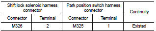
2.CHECK CVT SHIFT SELECTOR HARNESS (PART 2)
Check the continuity between the shift lock solenoid harness connector terminal and the park position switch harness connector terminal.
Is the inspection result normal? YES >> GO TO 3.
NO >> Replace the CVT shift selector harness. Refer to TM-482, "Disassembly and Assembly".
3.CHECK CVT SHIFT SELECTOR HARNESS (PART 3)
Check the continuity between the park switch harness connector terminal and the CVT shift selector harness connector terminal
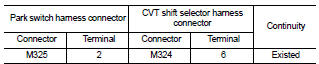
Is the inspection result normal? YES >> GO TO 4.
NO >> Replace the CVT shift selector harness. Refer to TM-482, "Disassembly and Assembly".
4.CHECK CVT SHIFT SELECTOR HARNESS (PART 4)
Check harness cladding CVT shift selector harness for damage.
Is the inspection result normal? YES >> INSPECTION END
NO >> Replace the CVT shift selector harness. Refer to TM-482, "Disassembly and Assembly".
Component Inspection (Stop Lamp Switch)
1.CHECK STOP LAMP SWITCH
Check the continuity between the stop lamp switch connector terminals.
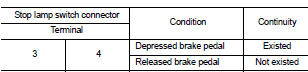
Is the inspection result normal? YES >> INSPECTION END
NO >> Replace stop lamp switch. Refer to BR-20, "Exploded View" (LHD) or BR-88, "Exploded View" (RHD).
 Shift position indicator circuit
Component Parts Function Inspection
1.CHECK SHIFT POSITION INDICATOR
1. Start the engine.
2. Shift selector lever.
3. Check that the selector lever position and the shift position indicator on
t ...
 Symptom diagnosis
CVT CONTROL SYSTEM
Symptom Table
The diagnosis item number indicates the order of check. Start checking in the
order from 1.
...
Other materials:
B2581, B2582 intake sensor
DTC Logic
DTC DETECTION LOGIC
NOTE:
• If DTC is displayed along with DTC U1000, first perform the trouble diagnosis
for DTC U1000. Refer to HAC-
51, "DTC Logic".
• If DTC is displayed along with DTC U1010, first perform the trouble diagnosis
for DTC U1010. HAC-52,
"DTC L ...
Inspection
INSPECTION AFTER REMOVAL
Appearance
Check the propeller shaft for bend and damage. If damage is detected, replace
propeller shaft assembly.
Propeller Shaft Runout
Check propeller shaft runout at measuring points with a dial indicator.
If runout exceeds specifications, replace propeller sh ...
Headlamp washer pump
Exploded View
1. Front washer nozzle LH
2. Front washer nozzle RH
3. Front washer tube LH
4. Front washer tube RH
5. Check valve
6. Front washer tube
7. Joint
8. Washer tank inlet cap
9. Washer tank inlet
10. Washer tank
11. Headlamp washer pump
12. Washer pump
13. Packing
1 ...
