Nissan Juke Service and Repair Manual : B2581, B2582 intake sensor
DTC Logic
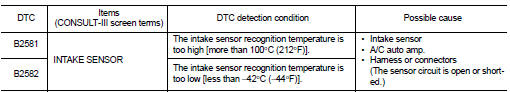
DTC DETECTION LOGIC
NOTE
:
• If DTC is displayed along with DTC U1000, first perform the trouble diagnosis
for DTC U1000. Refer to HAC-
51, "DTC Logic".
• If DTC is displayed along with DTC U1010, first perform the trouble diagnosis for DTC U1010. HAC-52, "DTC Logic".
DTC CONFIRMATION PROCEDURE
1.PERFORM DTC CONFIRMATION PROCEDURE
 With CONSULT-III
1. Turn ignition switch ON.
2. Select “Self Diagnostic Result” mode of “HVAC” using CONSULT-III.
3. Check DTC.
Is DTC detected? YES >> Refer to HAC-59, "Diagnosis Procedure".
NO >> INSPECTION END
Diagnosis Procedure
1.CHECK INTAKE SENSOR POWER SUPPLY
1. Turn ignition switch OFF.
2. Disconnect intake sensor connector.
3. Turn ignition switch ON.
4. Check voltage between intake sensor harness connector and ground.
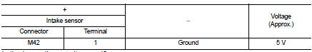
Is the inspection result normal? YES >> GO TO 2.
NO >> GO TO 4.
2.CHECK INTAKE SENSOR GROUND CIRCUIT FOR OPEN
1. Turn ignition switch OFF.
2. Disconnect A/C auto amp. connector.
3. Check continuity between intake sensor harness connector and A/C auto amp harness connector.
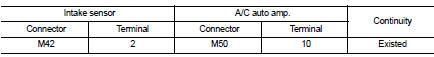
Is the inspection result normal?
YES >> GO TO 3.
NO >> Repair harness or connector.
3.CHECK INTAKE SENSOR
Check intake sensor. Refer to HAC-57, "Component Inspection".
Is the inspection result normal? YES >> Replace A/C auto amp. Refer to HAC-91, "Removal and Installation".
NO >> Replace intake sensor. Refer to HAC-95, "Removal and Installation".
4.CHECK INTAKE SENSOR POWER SUPPLY CIRCUIT FOR OPEN
1. Turn ignition switch OFF.
2. Disconnect A/C auto amp. connector.
3. Check continuity between intake sensor harness connector and A/C auto amp. harness connector.
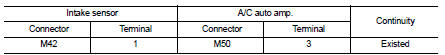
Is the inspection result normal? YES >> GO TO 5.
NO >> Repair harness or connector.
5.CHECK INTAKE SENSOR POWER SUPPLY CIRCUIT FOR SHORT
Check continuity between intake sensor harness connector and ground.
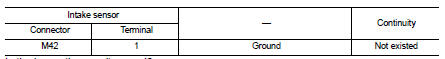
Is the inspection result normal? YES >> Replace A/C auto amp. Refer to HAC-91, "Removal and Installation".
NO >> Repair harness or connector.
Component Inspection
1.CHECK INTAKE SENSOR
1. Remove intake sensor. Refer to HAC-95, "Removal and Installation".
2. Check resistance between intake sensor terminals. Refer to applicable table for the normal value.
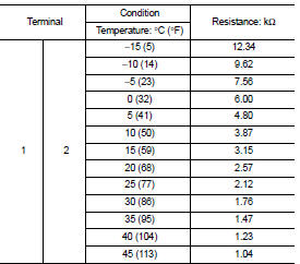
Is the inspection result normal? YES >> INSPECTION END
NO >> Replace intake sensor. Refer to HAC-95, "Removal and Installation".
 B257B, B257C ambient sensor
DTC Logic
DTC DETECTION LOGIC
NOTE:
• If DTC is displayed along with DTC U1000, first perform the trouble diagnosis
for DTC U1000. Refer to HAC-
51, "DTC Logic".
• If DTC is displ ...
 B2630, B2631 sunload sensor
DTC Logic
DTC DETECTION LOGIC
NOTE:
• If DTC is displayed along with DTC U1000, first perform the trouble diagnosis
for DTC U1000. Refer to HAC-
51, "DTC Logic".
• If DTC is displ ...
Other materials:
S mode indicator
Component Function Check
1.CHECK S MODE INDICATOR FUNCTION
Check S mode indicator turns ON for approx. 2 seconds when ignition switch
turns ON.
Is the inspection results normal?
YES >> INSPECTION END
NO >> Go to TM-469, "Diagnosis Procedure".
Diagnosis Procedure
1.CH ...
Oil filter
Removal and Installation
REMOVAL
1. Remove engine under cover.
2. Using oil filter wrench [SST: KV10115801] (A), remove oil filter.
: Vehicle front
CAUTION:
• Oil filter is provided with relief valve. Use genuine NISSAN
oil filter or equivalent.
• Be careful not to get burned when engine ...
B1089 seat belt Pre-tensioner LH
DTC Logic
DTC DETECTION LOGIC
DTC CONFIRMATION PROCEDURE
1.CHECK SELF-DIAG RESULT
With CONSULT-III
1. Turn ignition switch ON.
2. Perform “Self Diagnostic Result” mode of “AIR BAG” using CONSULT-III.
Without CONSULT-III
1. Turn ignition switch ON.
2. Check the air bag warning la ...
