Nissan Juke Service and Repair Manual : B2630, B2631 sunload sensor
DTC Logic
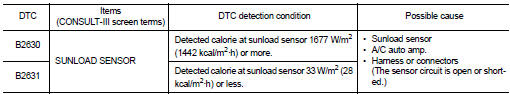
DTC DETECTION LOGIC
NOTE
:
• If DTC is displayed along with DTC U1000, first perform the trouble diagnosis
for DTC U1000. Refer to HAC-
51, "DTC Logic".
• If DTC is displayed along with DTC U1010, first perform the trouble diagnosis for DTC U1010. HAC-52, "DTC Logic".
• Sunload sensor may register a malfunction when indoors, at dusk, or at other times when light is insufficient.
When performing the diagnosis indoors, use a lamp (60 W or more) that is pointed at the sunload sensor.
DTC CONFIRMATION PROCEDURE
1.PERFORM DTC CONFIRMATION PROCEDURE
With CONSULT-III
1. Turn ignition switch ON.
2. Select “Self Diagnostic Result” mode of “HVAC” using CONSULT-III.
3. Check DTC.
Is DTC detected? YES >> Refer to HAC-62, "Diagnosis Procedure".
NO >> INSPECTION END
Diagnosis Procedure
1.CHECK SUNLOAD SENSOR POWER SUPPLY
1. Turn ignition switch OFF.
2. Disconnect sunload sensor connector.
3. Turn ignition switch ON.
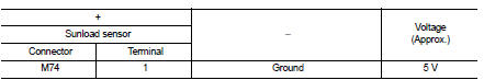
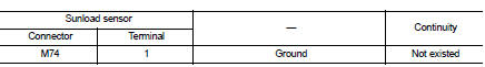
4. Check voltage between sunload sensor harness connector and ground.
Is the inspection result normal? YES >> GO TO 2.
NO >> GO TO 4.
2.CHECK SUNLOAD SENSOR GROUND CIRCUIT FOR OPEN
1. Turn ignition switch OFF.
2. Disconnect A/C auto amp. connector.
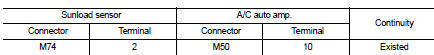
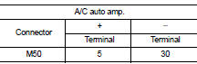
3. Check continuity between sunload sensor harness connector and A/C auto amp harness connector.
Is the inspection result normal? YES >> GO TO 3.
NO >> Repair harness or connector.
3.CHECK SUNLOAD SENSOR
1. Disconnect A/C auto amp. connector.
2. Check sunload sensor. Refer to HAC-57, "Component Inspection".
Is the inspection result normal? YES >> Replace A/C auto amp. Refer to HAC-91, "Removal and Installation".
NO >> Replace sunload sensor. Refer to HAC-94, "Removal and Installation".
4.CHECK SUNLOAD SENSOR POWER SUPPLY CIRCUIT FOR OPEN
1. Turn ignition switch OFF.
2. Disconnect A/C auto amp. connector.
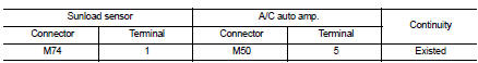
3. Check continuity between sunload sensor harness connector and A/C auto amp. harness connector.
Is the inspection result normal? YES >> GO TO 5.
NO >> Repair harness or connector.
5.CHECK SUNLOAD SENSOR POWER SUPPLY CIRCUIT FOR SHORT
Check continuity between sunload sensor harness connector and ground.
Is the inspection result normal? YES >> Replace A/C auto amp. Refer to HAC-91, "Removal and Installation".
NO >> Repair harness or connector.
Component Inspection
1.CHECK SUNLOAD SENSOR
1. Turn ignition switch ON.
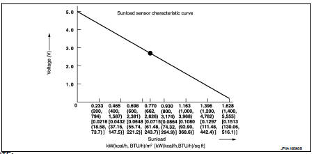
2. Check voltage between A/C auto amp. harness connector and ground. Refer to applicable table for the normal value.
NOTE
:
• When checking indoors, use a lamp of approximately 60 W. Move the lamp towards
and away from the
sensor to check.
• The sunload amount produced by direct sunshine in fair weather is equivalent to approximately 0.77 kW/m2 (662 kcal/m2·h).
Is the inspection result normal? YES >> INSPECTION END
NO >> Replace sunload sensor. Refer to HAC-94, "Removal and Installation".
 B2581, B2582 intake sensor
DTC Logic
DTC DETECTION LOGIC
NOTE:
• If DTC is displayed along with DTC U1000, first perform the trouble diagnosis
for DTC U1000. Refer to HAC-
51, "DTC Logic".
• If DTC is displ ...
 B27A0, B27A1 intake door motor
DTC Logic
DTC DETECTION LOGIC
NOTE:
• If DTC is displayed along with DTC U1000, first perform the trouble diagnosis
for DTC U1000. Refer to HAC-
51, "DTC Logic".
• If DTC is displ ...
Other materials:
P1813 4WD mode switch
DTC Logic
DTC DETECTION LOGIC
DTC CONFIRMATION PROCEDURE
1.PRECONDITIONING
If “DTC CONFIRMATION PROCEDURE” has been previously conducted, always turn
ignition switch OFF and
wait at least 10 seconds before conducting the next test.
>> GO TO 2.
2.DTC REPRODUCTION PROCEDURE
W ...
NISSAN Intelligent Key
NISSAN Intelligent Key fob (supplied as two complete sets)
Emergency mechanical key (integrated inside the fob)
Key number plate (one unique metal stamp plate)
Your vehicle is protected by advanced security pairing, meaning it can only be ...
Filament
Inspection and Repair
INSPECTION
1. When measuring voltage, wrap tin foil around the top of the negative
probe. Then press the foil against the wire with your finger.
2. Attach probe circuit tester (in Volt range) to middle portion of
each filament.
3. If a filament is burned out, circuit ...
