Nissan Juke Service and Repair Manual : B257B, B257C ambient sensor
DTC Logic
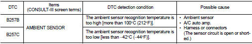
DTC DETECTION LOGIC
NOTE
:
• If DTC is displayed along with DTC U1000, first perform the trouble diagnosis
for DTC U1000. Refer to HAC-
51, "DTC Logic".
• If DTC is displayed along with DTC U1010, first perform the trouble diagnosis for DTC U1010. HAC-52, "DTC Logic".
DTC CONFIRMATION PROCEDURE
1.PERFORM DTC CONFIRMATION PROCEDURE
 With CONSULT-III
1. Turn ignition switch ON.
2. Select “Self Diagnostic Result” mode of “HVAC” using CONSULT-III.
3. Check DTC.
Is DTC detected? YES >> Refer to HAC-56, "Diagnosis Procedure".
NO >> INSPECTION END
Diagnosis Procedure
1.CHECK AMBIENT SENSOR POWER SUPPLY
1. Turn ignition switch OFF.
2. Disconnect ambient sensor connector.
3. Turn ignition switch ON.
4. Check voltage between ambient sensor harness connector and ground.
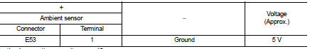
Is the inspection result normal? YES >> GO TO 2.
NO >> GO TO 4.
2.CHECK AMBIENT SENSOR GROUND CIRCUIT FOR OPEN
1. Turn ignition switch OFF.
2. Disconnect A/C auto amp. connector.
3. Check continuity between ambient sensor harness connector and A/C auto amp harness connector.
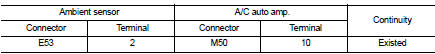
Is the inspection result normal?
YES >> GO TO 3.
NO >> Repair harness or connector.
3.CHECK AMBIENT SENSOR
Check ambient sensor. Refer to HAC-57, "Component Inspection".
Is the inspection result normal? YES >> Replace A/C auto amp. Refer to HAC-91, "Removal and Installation".
NO >> Replace ambient sensor. Refer to HAC-92, "Removal and Installation".
4.CHECK AMBIENT SENSOR POWER SUPPLY CIRCUIT FOR OPEN
1. Turn ignition switch OFF.
2. Disconnect A/C auto amp. connector.
3. Check continuity between ambient sensor harness connector and A/C auto amp. harness connector.
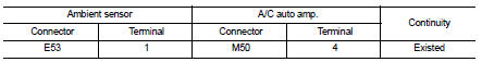
Is the inspection result normal? YES >> GO TO 5.
NO >> Repair harness or connector.
5.CHECK AMBIENT SENSOR POWER SUPPLY CIRCUIT FOR SHORT
Check continuity between ambient sensor harness connector and ground.
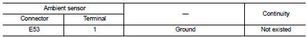
Is the inspection result normal? YES >> Replace A/C auto amp. Refer to HAC-91, "Removal and Installation".
NO >> Repair harness or connector.
Component Inspection
1.CHECK AMBIENT SENSOR
1. Remove ambient sensor. Refer to HAC-92, "Removal and Installation".
2. Check resistance between ambient sensor terminals. Refer to applicable table for the normal value.
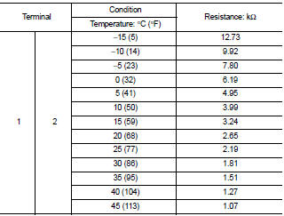
Is the inspection result normal? YES >> INSPECTION END
NO >> Replace ambient sensor. Refer to HAC-92, "Removal and Installation".
 B2578, B2579 In-vehicle sensor
DTC Logic
DTC DETECTION LOGIC
NOTE:
• If DTC is displayed along with DTC U1000, first perform the trouble diagnosis
for DTC U1000. Refer to HAC-
51, "DTC Logic".
• If DTC is displ ...
 B2581, B2582 intake sensor
DTC Logic
DTC DETECTION LOGIC
NOTE:
• If DTC is displayed along with DTC U1000, first perform the trouble diagnosis
for DTC U1000. Refer to HAC-
51, "DTC Logic".
• If DTC is displ ...
Other materials:
Operation inspection
Work Procedure
The purpose of the operational check is to check that the individual system
operates normally.
Check condition : Engine running at normal operating temperature.
1.CHECK MEMORY FUNCTION
1. Set temperature to 30°C by operating the temperature control dial.
2. Press OFF switch.
...
Security indicator lamp does not turn on or blink
Description
Security indicator lamp does not blink when ignition switch is in a position
other than ON.
NOTE:
• Before performing the diagnosis, check “Work Flow”. Refer to SEC-47, "Work
Flow".
• Check that vehicle is under the condition shown in “CONDITIONS OF VEHICLE ...
Service data and specifications (SDS)
Compressor
Lubricant
Refrigerant
Engine Idling Speed
Refer to EC-807, "Idle Speed".
Belt Tension
Refer to EM-154, "Checking". ...
