Nissan Juke Service and Repair Manual : B2578, B2579 In-vehicle sensor
DTC Logic
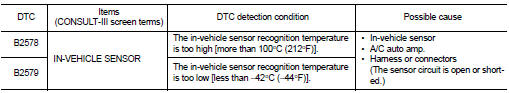
DTC DETECTION LOGIC
NOTE
:
• If DTC is displayed along with DTC U1000, first perform the trouble diagnosis
for DTC U1000. Refer to HAC-
51, "DTC Logic".
• If DTC is displayed along with DTC U1010, first perform the trouble diagnosis for DTC U1010. HAC-52, "DTC Logic".
DTC CONFIRMATION PROCEDURE
1.PERFORM DTC CONFIRMATION PROCEDURE
With CONSULT-III
1. Turn ignition switch ON.
2. Select “Self Diagnostic Result” mode of “HVAC” using CONSULT-III.
3. Check DTC.
Is DTC detected? YES >> Refer to HAC-53, "Diagnosis Procedure".
NO >> INSPECTION END
Diagnosis Procedure
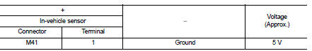
1.CHECK IN-VEHICLE SENSOR POWER SUPPLY
1. Turn ignition switch OFF.
2. Disconnect in-vehicle sensor connector.
3. Turn ignition switch ON.
4. Check voltage between in-vehicle sensor harness connector and ground.
Is the inspection result normal? YES >> GO TO 2.
NO >> GO TO 4.
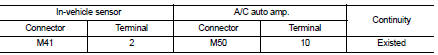
2.CHECK IN-VEHICLE SENSOR GROUND CIRCUIT FOR OPEN
1. Turn ignition switch OFF.
2. Disconnect A/C auto amp. connector.
3. Check continuity between in-vehicle sensor harness connector and A/C auto amp harness connector.
Is the inspection result normal?
YES >> GO TO 3.
NO >> Repair harness or connector.
3.CHECK IN-VEHICLE SENSOR
Check in-vehicle sensor. Refer to HAC-57, "Component Inspection".
Is the inspection result normal? YES >> Replace A/C auto amp. Refer to HAC-91, "Removal and Installation".
NO >> Replace in-vehicle sensor. Refer to HAC-93, "Removal and Installation".
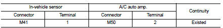
4.CHECK IN-VEHICLE SENSOR POWER SUPPLY CIRCUIT FOR OPEN
1. Turn ignition switch OFF.
2. Disconnect A/C auto amp. connector.
3. Check continuity between in-vehicle sensor harness connector and A/C auto amp. harness connector.
Is the inspection result normal? YES >> GO TO 5.
NO >> Repair harness or connector.
5.CHECK IN-VEHICLE SENSOR POWER SUPPLY CIRCUIT FOR SHORT
Check continuity between in-vehicle sensor harness connector and ground.
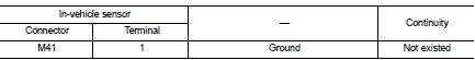
Is the inspection result normal? YES >> Replace A/C auto amp. Refer to HAC-91, "Removal and Installation".
NO >> Repair harness or connector.
Component Inspection
1.CHECK IN-VEHICLE SENSOR
1. Remove in-vehicle sensor. Refer to HAC-93, "Removal and Installation".
2. Check resistance between in-vehicle sensor terminals. Refer to applicable table for the normal value.
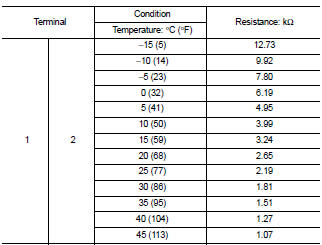
Is the inspection result normal? YES >> INSPECTION END
NO >> Replace in-vehicle sensor. Refer to HAC-93, "Removal and Installation".
 U1010 control unit (CAN)
Description
Initial diagnosis of A/C auto amp.
DTC Logic
DTC DETECTION LOGIC
DTC CONFIRMATION PROCEDURE
1.PERFORM DTC CONFIRMATION PROCEDURE
With CONSULT-III
1. Turn ignition switch ON.
2. S ...
 B257B, B257C ambient sensor
DTC Logic
DTC DETECTION LOGIC
NOTE:
• If DTC is displayed along with DTC U1000, first perform the trouble diagnosis
for DTC U1000. Refer to HAC-
51, "DTC Logic".
• If DTC is displ ...
Other materials:
P1614 chain of IMMU-KEY
DTC Logic
DTC DETECTION LOGIC
DTC CONFIRMATION PROCEDURE
1.PERFORM DTC CONFIRMATION PROCEDURE 1
1. Contact Intelligent Key backside to push-button ignition switch.
2. Check DTC in “Self Diagnostic Result” mode of “ENGINE” using CONSULT-III.
Is DTC detected?
YES >> Go to SEC- ...
Emission control not satisfactory
Description
CHART 22: EMISSION CONTROL NOT SATISFACTORY
Diagnosis Procedure
1.CHECK ECM POWER SUPPLY AND GROUND CIRCUIT
Check ECM power supply and ground circuit. Refer to EC-885, "Diagnosis
Procedure".
Is the inspection result normal?
YES >> GO TO 2.
NO >> Repair ...
B2110 shift position/clutch interlock switch
DTC Logic
DTC DETECTION LOGIC
NOTE:
If DTC B2110 is displayed with DTC U1000, first perform the trouble diagnosis
for DTC U1000. Refer to PCS-
30, "DTC Logic".
DTC CONFIRMATION PROCEDURE
1.PERFORM DTC CONFIRMATION PROCEDURE
1. Shift selector lever to the P position.
2. Turn ign ...
