Nissan Juke Service and Repair Manual : Service data and specifications (SDS)
Wheel Bearing

Drive Shaft
2WD
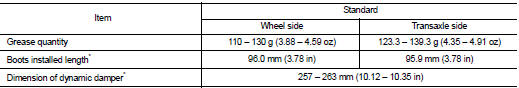
*: For measuring position, refer to FAX-26, "WHEEL SIDE : Disassembly and Assembly" (Wheel side), FAX- 29, "TRANSAXLE SIDE : Disassembly and Assembly" (Transaxle side).
4WD
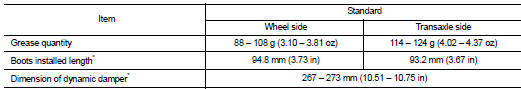
*: For measuring position, refer to FAX-26, "WHEEL SIDE : Disassembly and Assembly" (Wheel side), FAX- 29, "TRANSAXLE SIDE : Disassembly and Assembly" (Transaxle side).
 Inspection
INSPECTION AFTER REMOVAL
Check the following items, and replace the part if necessary.
• Move joint up/down, left/right, and in the axial directions. Check for motion
that is not smooth and fo ...

Other materials:
NISSAN dynamic control system
NISSAN dynamic control system : System
Diagram
CVT models
M/T models
NISSAN dynamic control system : System
Description
CVT models
System Description
TCM transmits a drive mode select signal to ECM via CAN communication, according
to a NORMAL mode
signal, SPORT mode signal, or ECO mo ...
Uniform tire quality grading
The Department of Transportation (DOT) mandates Quality Grades for all passenger car tires. All tires must conform to stringent federal safety requirements in addition to these comparative performance grades.
These quality grades are embossed on the tire sidewall, located in the area between th ...
Windshield-washer fluid
Maintain clear visibility by checking and filling the windshield-washer fluid reservoir periodically. You should replenish the reservoir promptly when the "Low Washer Fluid" notification appears on the Nissan Leaf vehicle information display.
For more details on interpreti ...
