Nissan Juke Service and Repair Manual : Wiring diagram
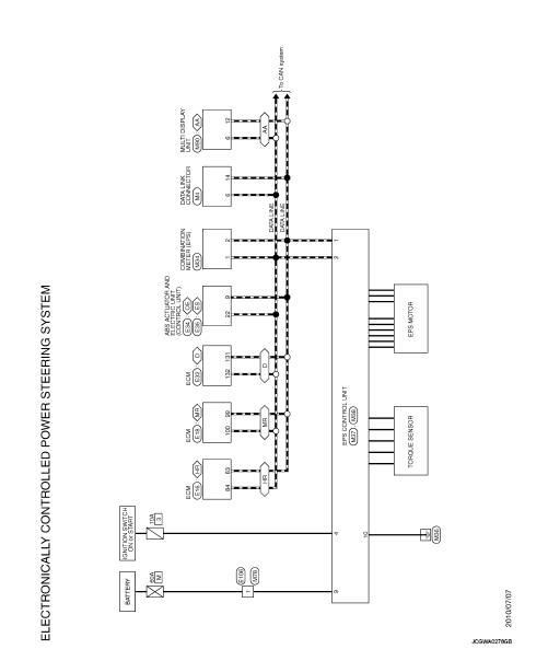
ELECTRONICALLY CONTROLLED POWER STEERING SYSTEM
Wiring Diagram
For connector terminal arrangements, harness layouts, and alphabets in a
(option abbreviation; if not
described in wiring diagram), refer to GI-12, "Connector Information/Explanation
of Option Abbreviation".
 ECU diagnosis information
EPS control unit
Reference Value
VALUES ON THE DIAGNOSIS TOOL
CAUTION:
The output signal indicates the EPS control unit calculation data. The normal
values will be displayed
even in the event t ...
 Basic inspection
DIAGNOSIS AND REPAIR WORKFLOW
Work Flow
DETAILED FLOW
1.INTERVIEW FROM THE CUSTOMER
Clarify customer complaints before inspection. First of all, perform an
interview utilizing STC-17, "Diag ...
Other materials:
Additional service when removing battery negative terminal
Description
• The audio unit is equipped with the anti-theft system.
• The audio unit operates after authenticating a fixed four-digit anti-theft
code.
• After removing the battery of the audio unit, the authentication of the
anti-theft code is required.
Work Procedure
1.POWER SWITCH ...
B1023 passenger air bag off indicator
DTC Logic
DTC DETECTION LOGIC
DTC CONFIRMATION PROCEDURE
1.CHECK SELF-DIAG RESULT
With CONSULT-III
1. Turn ignition switch ON.
2. Perform “Self Diagnostic Result” mode of “AIR BAG” using CONSULT-III.
Without CONSULT-III
1. Turn ignition switch ON.
2. Check the air bag warning la ...
No engine braking
Description
CHART 11: NO ENGINE BRAKING
Diagnosis Procedure
1.CHECK ECM POWER SUPPLY AND GROUND CIRCUIT
Check ECM power supply and ground circuit. Refer to EC-885, "Diagnosis
Procedure".
Is the inspection result normal?
YES >> GO TO 2.
NO >> Repair or replace harne ...
