Nissan Juke Service and Repair Manual : Basic inspection
DIAGNOSIS AND REPAIR WORKFLOW
Work Flow
DETAILED FLOW
1.INTERVIEW FROM THE CUSTOMER
Clarify customer complaints before inspection. First of all, perform an interview utilizing STC-17, "Diagnostic Work Sheet" and reproduce symptoms as well as fully understand it. Ask customer about his/her complaints carefully. Check symptoms by driving vehicle with customer, if necessary.
CAUTION:
Customers are not professional. Never guess easily like “maybe the customer
means that...,” or
“maybe the customer mentions this symptom”.
>> GO TO 2.
2.CHECK SYMPTOM
Reproduce the symptom that is indicated by the customer, based on the information from the customer obtained by interview. Also check that the symptom is not caused by protection function. Refer to STC-13, "Protection Function".
CAUTION:
When the symptom is caused by normal operation, fully inspect each portion and
obtain the understanding
of customer that the symptom is not caused by a malfunction.
>> GO TO 3.
3.PERFORM SELF-DIAGNOSIS
 With CONSULT-III
Perform self-diagnosis for “EPS”.
Is any DTC detected? YES >> Record or print self-diagnosis results. GO TO 4.
NO >> GO TO 6.
 With CONSULT-III
1. Erase self-diagnostic results for “EPS”.
2. Perform DTC confirmation procedures for the error detected system.
NOTE
:
If some DTCs are detected at the same time, determine the order for performing
the diagnosis based on STC-
13, "DTC Inspection Priority Chart".
Is any DTC detected? YES >> GO TO 5.
NO >> Check harness and connectors based on the information obtained by interview. Refer to GI-42, "Intermittent Incident".
5.REPAIR OR REPLACE ERROR-DETECTED PARTS
• Repair or replace error-detected parts.
• Reconnect part or connector after repairing or replacing.
• When DTC is detected, erase self-diagnostic results for “EPS”.
>> GO TO 7.
6.IDENTIFY ERROR-DETECTED SYSTEM BY SYMPTOM DIAGNOSIS
Estimate error-detected system based on symptom diagnosis and perform inspection.
Can the error-detected system be identified?
NO >> Check harness and connectors based on the information obtained by interview. Refer to GI-42, "Intermittent Incident".
7.FINAL CHECK
With CONSULT-III
1. Check the reference value for EPS control unit.
2. Recheck the symptom and check that symptom is not reproduced on the same conditions.
Is the symptom reproduced? YES >> GO TO 3.
NO >> INSPECTION END
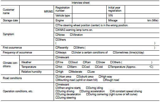
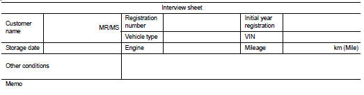
Diagnostic Work Sheet
Description
• In general, customers have their own criteria for a problem. Therefore, it is
important to understand the
symptom and status well enough by asking the customer about his/her concerns
carefully. To systemize all
the information for the diagnosis, prepare the interview sheet referring to the
interview points.
• In some cases, multiple conditions that appear simultaneously may cause a DTC to be detected.
Interview sheet sample
 Wiring diagram
ELECTRONICALLY CONTROLLED POWER STEERING SYSTEM
Wiring Diagram
For connector terminal arrangements, harness layouts, and alphabets in a
(option abbreviation; if not
described in wiring diagram), ...

Other materials:
To protect your vehicle from corrosion
• Wash and wax your vehicle often to keep the vehicle clean.• • Always check
for minor damage to the paint and repair it as soon as possible.• • Keep drain
holes at the bottom of the doors open to avoid water accumulation.• • Check the
underbody for accumulation of sand, di ...
Intake manifold
Exploded View
1. Clamp
2. Water hose
3. PCV hose
4. Clamp
5. Gasket
6. Intake manifold
7. Clamp
8. Vacuum hose
9. Vacuum gallery assembly
10. Clamp
11. EVAP hose
12. EVAP service port valve
13. EVAP hose
14.EVAP canister purge volume control
solenoid valve
15. Bracket
16 ...
Maintenance precautions
When performing any inspection or maintenance work on your Nissan Leaf, it is imperative to prioritize safety to prevent serious accidental injury to yourself or damage to the vehicle's sophisticated components. The following general precautions represent essential safety standards that must be obse ...
