Nissan Juke Owners Manual : Difference between predictive and actual distances
Backing up on a steep uphill
When backing up the vehicle up a hill, the distance guide lines and the vehicle width guide lines are shown closer than the actual distance.
For example, the display shows 3 ft (1 m) to the placeA , but the actual 3 ft (1 m) distance on the hill is the placeB . Note that any object on the hill is viewed in the monitor further than it appears.
Backing up on a steep downhill
When backing up the vehicle down a hill, the distance guide lines and the vehicle width guide lines are shown further than the actual distance.
For example, the display shows 3 ft (1 m) to the placeA , but the actual 3 ft (1 m) distance on the hill is the placeB . Note that any object on the hill is viewed in the monitor closer than it appears.
Backing up near a projecting object
The vehicle may seem to nearly clear the object in the display. However, the vehicle may hit the object if it projects over the actual backing up course.
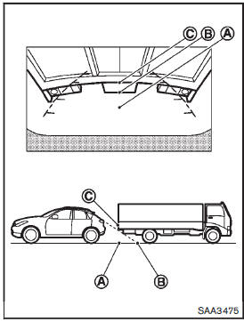
Backing up behind a projecting object The position C is shown further than the position B in the display. However, the position C is actually at the same distance as the position A . The vehicle may hit the object when backing up to the position A if the object projects over the actual backing up course.
 How to read the displayed lines
Guiding lines which indicate the vehicle width and distances to objects with
reference to the bumper lineA are displayed on the monitor.
Distance guide lines:
Indicate distances from the bumper. ...
 Operating tips
• When the shift lever is shifted to the R (Reverse) position, the monitor screen
automatically changes to the RearView Monitor mode. However, the radio can be heard.
• When the view is switche ...
Other materials:
C1110 ABS actuator and electric unit (control unit)
DTC Logic
DTC DETECTION LOGIC
DTC CONFIRMATION PROCEDURE
1.PRECONDITIONING
If “DTC CONFIRMATION PROCEDURE” has been previously conducted, always turn
ignition switch OFF and
wait at least 10 seconds before conducting the next test.
>> GO TO 2.
2.CHECK DTC DETECTION
With CON ...
Door request switch
Component Function Check
1.CHECK FUNCTION
1. Select “INTELLIGENT KEY” of “BCM” using CONSULT-III.
2. Select “REQ SW-DR”, “REQ SW-AS” in “DATA MONITOR” mode.
3. Check that the function operates normally according to the following
conditions.
Is the inspection result norma ...
Service information for electrical incident
Work Flow
WORK FLOW
Control Units and Electrical Parts
PRECAUTIONS
• Never reverse polarity of battery terminals.
• Install only parts specified for a vehicle.
• Before replacing the control unit, check the input and output and functions of
the component parts.
• Do not apply ex ...
