Nissan Juke Service and Repair Manual : System
POWER WINDOW SYSTEM
POWER WINDOW SYSTEM : System Diagram
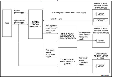
POWER WINDOW SYSTEM : System Description
• Power window system is activated by power window switch when ignition switch turns ON.
• Power window main switch opens/closes all door glass.
• Front and rear power window switch opens/closes the corresponding door glass.
• AUTO UP/DOWN operation can be performed when power window main switch turns to AUTO.
• Power window lock switch can lock all power windows other than driver seat.
• If door glass receives resistance that is the specified value or more while power window of driver seat is in AUTO-UP operation, power window of driver seat operates in the reverse direction.
POWER WINDOW AUTO-OPERATION (FRONT DRIVER SIDE)
• AUTO UP/DOWN operation can be performed when power window main switch turns to AUTO.
• Encoder continues detecting the movement of power window motor and transmits to power window switch as the encoder pulse signal while power window motor is operating.
• Power window switch reads the changes of encoder signal and stops AUTO operation when door glass is at fully opened/closed position.
• Power window motor is operable in case encoder is malfunctioning.
POWER WINDOW LOCK
Ground circuit inside power window main switch shuts off when power window lock switch is ON. This inhibits power window switch operation except with the power window main switch.
ANTI-PINCH SYSTEM (FRONT DRIVER SIDE)
• Pinch foreign material in the door glass during AUTO-UP operation, and it is the anti-pinch function that lowers the door glass 150 mm (5.9 in) when detected.
• Encoder continues detecting the movement of front power window motor (driver side) and transmits to power window main switch as the encoder pulse signal while front power window motor (driver side) is operating.
• Resistance is applied to the front power window motor (driver side) rotation that changes the frequency of encoder pulse signal if foreign material is trapped in the door glass.
• Power window main switch controls to lower the window glass for 150 mm (5.9 in) after it detects encoder pulse signal frequency change.
OPERATION CONDITION
• When front door glass (driver side) AUTO-UP operation is performed (anti-pinch function does not operate just before the door glass closes and is fully closed) NOTE
:
Depending on environment and driving conditions, if a similar impact or load is
applied to the door glass, it
may lower.
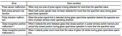
Fail Safe
FAIL-SAFE CONTROL
Switches to fail-safe control when malfunction is detected in encoder signal that detects up/down speed and direction of door glass. Switches to fail-safe control when error beyond regulation value is detected between the fully closed position and the actual position of the glass.
It changes to condition before initialization and the following functions do not operate when switched to failsafe control.
• Auto-up operation
• Anti-pinch function
Perform initial operation to recover when switched to fail-safe mode. However, it switches back to fail-safe control when malfunction is found in power window main switch or front power window motor (driver side).
 Component parts
Component Parts Location
1. BCM
Refer to BCS-6, "BODY CONTROL
SYSTEM : Component Parts Location"
(with Intelligent Key) or BCS-96,
"BODY CONTROL SYSTEM : Component
Parts Locatio ...

Other materials:
Precaution for Supplemental Restraint System (SRS) "AIR BAG" and "SEAT BELT
PRE-TENSIONER"
The Supplemental Restraint System such as “AIR BAG” and “SEAT BELT PRE-TENSIONER”,
used along
with a front seat belt, helps to reduce the risk or severity of injury to the
driver and front passenger for certain
types of collision. Information necessary to service the system safely is
...
Back door does not opened
Diagnosis Procedure
1.CHECK BACK DOOR OPENER SWITCH
Check back door opener switch.
Refer to DLK-244, "Component Function Check".
Is the inspection result normal?
YES >> GO TO 2.
NO >> Repair or replace the malfunctioning parts.
2.CHECK BACK DOOR OPENER ACTUATOR
...
Approaching Vehicle Sound for Pedestrians (VSP) system
The Approaching Vehicle Sound for Pedestrians (VSP) system is a sophisticated safety feature designed to enhance awareness for those around you. Because the electric powertrain of the Nissan Leaf is exceptionally quiet, this system generates an audible sound signature to alert ...
