Nissan Juke Service and Repair Manual : ECU diagnosis information
EPS control unit
Reference Value
VALUES ON THE DIAGNOSIS TOOL
CAUTION:
The output signal indicates the EPS control unit calculation data. The normal
values will be displayed
even in the event that the output circuit (harness) is open.
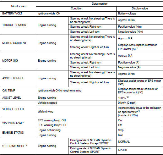
*1: Almost in accordance with the value of “MOTOR SIG”. It is not a malfunction though these values are not accorded when steering quickly.
*2: Normally displays 100%. In case of an excessive stationary steering, the assist curvature gradually falls. However, it returns to 100% when left standing.
*3: It is not a malfunction, though it might not be corresponding just after ignition switch in turned ON.
*4: Displays NORMAL in models without Nissan Dynamic Control System.
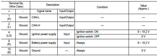
TERMINAL LAYOUT
PHYSICAL VALUES
Fail-Safe
• If any malfunction occurs in the system, and control unit detects the malfunction, EPS warning lamp on combination meter turns ON to indicate system malfunction.
• When EPS warning lamp is ON, enters into a manual steering state. (Control turning force steering wheel becomes heavy.)
Protection Function
EPS control unit decreases the output signal to EPS motor while extremely using the power steering function (e.g., full steering) consecutively for protecting EPS motor and EPS control unit (Overload protection control).
While activating overload protection control, the assist torque gradually decreases, and the steering wheel turning force becomes heavy. The normal assist torque is recovered if the steering wheel is not turned for a while.
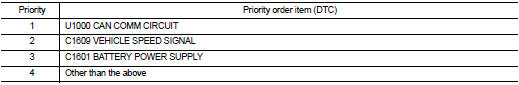
DTC Inspection Priority Chart
When multiple DTCs are detected simultaneously, check one by one depending on the following priority list.
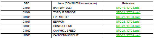
DTC Index
 Diagnosis system (EPS control unit)
Consult-III Function
FUNCTION
CONSULT-III can display each diagnostic item using the diagnostic test modes
shown following.
*: The following diagnosis information is erased by erasing.
• DTC ...
 Wiring diagram
ELECTRONICALLY CONTROLLED POWER STEERING SYSTEM
Wiring Diagram
For connector terminal arrangements, harness layouts, and alphabets in a
(option abbreviation; if not
described in wiring diagram), ...
Other materials:
How to trickle charge (AC 110-120 volt) by L1 & L2 EVSE
WARNING
If you use a pacemaker or an implantable cardiovascular defibrillator (ICD), you must maintain a distance of at least 6 inches (15 cm) from the EVSE (Electric Vehicle Supply Equipment) to prevent potential interference with your medical device.
Before initiating any c ...
U1000 can comm circuit
Description
CAN (Controller Area Network) is a serial communication line for real time
application. It is an on-vehicle multiplex
communication line with high data communication speed and excellent malfunction
detection ability.
Many electronic control units are equipped onto a vehicle, and ...
Oil filter
Removal and Installation
REMOVAL
1. Remove engine under cover.
2. Using oil filter wrench [SST: KV10115801 (J-38956)] (A), remove
oil filter.
: Vehicle front
CAUTION:
• Oil filter is provided with relief valve. Use genuine NISSAN
oil filter or equivalent.
• Be careful not to get burned ...
