
Nissan Juke Service and Repair Manual : Antenna base
Exploded View
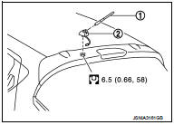
1. Antenna rod
2. Antenna base
 : N·m (kg-m, in-lb)
Removal and Installation
REMOVAL
1. Remove headlining. Refer to INT-26, "Exploded View".
2. Disconnect antenna feeder connector.
3. Remove nut to remove antenna base.
INSTALLATION
Install in the reverse order of removal.
CAUTION:
If the antenna base mounting nut is tightened looser than the specified torque,
then this will lower the
sensitivity of the antenna. On the other hand, if the nut is tightened tighter
than the specified torque,
then this will deform the roof panel.
 Rear door speaker
Removal and Installation
REMOVAL
1. Remove rear door finisher. Refer to INT-16, "Exploded View".
2. Remove rear door speaker screws, then disconnect rear door speaker connector
and remo ...
 GPS antenna
Feeder Layout
Removal and Installation
REMOVAL
1. Remove instrument panel. Refer to IP-12, "Exploded View".
2. Remove antenna feeder clip, then remove GPS antenna screw and remove GPS ...
Other materials:
Power supply routing circuit
Wiring Diagram - Battery power supply -
For connector terminal arrangements, harness layouts, and alphabets in a
(option abbreviation; if not
described in wiring diagram), refer to GI-12, "Connector Information/Explanation
of Option Abbreviation".
Wiring Diagram - Accessory p ...
U1000, U1001 CAN COMM CIRCUIT
Description
CAN (Controller Area Network) is a serial communication line for real time
application. It is an on-vehicle multiplex
communication line with high data communication speed and excellent error
detection ability. Many electronic
control units are equipped onto a vehicle, and each co ...
Vehicle information
Identification information
Japan production models
JAPAN PRODUCTION MODELS : Model Variation
Model variation code (Prefix and suffix designations)
JAPAN PRODUCTION MODELS : Information About Identification or Model Code
IDENTIFICATION NUMBER
1. Air conditioner specification label
2. Ve ...
