Nissan Juke Service and Repair Manual : Fuel pump
Component Function Check
1.CHECK FUEL PUMP FUNCTION
1. Turn ignition switch ON.
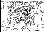
2. Pinch fuel feed hose with two fingers.
Fuel pressure pulsation should be felt on the fuel feed hose for 1 second after ignition switch is turned ON.
Is the inspection result normal? YES >> INSPECTION END
NO >> EC-780, "Diagnosis Procedure".
Diagnosis Procedure
1.CHECK FUEL PUMP POWER SUPPLY CIRCUIT-I
1. Turn ignition switch OFF.
2. Disconnect ECM harness connector.
3. Turn ignition switch ON.
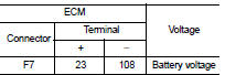
4. Check the voltage between ECM harness connector and ground.
Is the inspection result normal? YES >> GO TO 4.
NO >> GO TO 2.
2.CHECK FUEL PUMP POWER SUPPLY CIRCUIT-II
1. Turn ignition switch OFF.
2. Disconnect IPDM E/R harness connector.
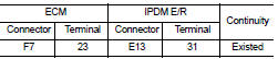
3. Check the continuity between IPDM E/R harness connector and ECM harness connector.
4. Also check harness for short to ground and short to power.
Is the inspection result normal? YES >> GO TO 10.
NO >> GO TO 3.
3.DETECT MALFUNCTIONING PART
Check the following.
ŌĆó Harness or connectors E8, F1 ŌĆó IPDM E/R connector E13 ŌĆó Harness for open or short to ground and short power
>> Repair open circuit or short to ground or short to power in harness or connectors.
4.CHECK FUEL PUMP POWER SUPPLY CIRCUIT-III
1. Turn ignition switch OFF.
2. Reconnect all harness connectors disconnected.
3. Disconnect ŌĆ£fuel level sensor unit and fuel pumpŌĆØ harness connector.
4. Turn ignition switch ON.
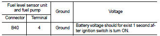
5. Check voltage between ŌĆ£fuel level sensor unit and fuel pumpŌĆØ harness connector and ground.
Is the inspection result normal? YES >> GO TO 8.
NO >> GO TO 5.
5.CHECK 15 A FUSE
1. Turn ignition switch OFF.
2. Disconnect 15 A fuse (No. 60) from IPDM E/R.
3. Check 15 A fuse.
Is the inspection result normal? YES >> GO TO 6.
NO >> Replace fuse.
6.CHECK FUEL PUMP POWER SUPPLY CIRCUIT-IV
1. Disconnect IPDM E/R harness connector.
2. Check the continuity between IPDM E/R harness connector and ŌĆ£fuel level sensor unit and fuel pumpŌĆØ harness connector.
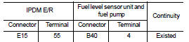
3. Also check harness for short to ground and short to power.
Is the inspection result normal? YES >> GO TO 10.
NO >> GO TO 7.
7.DETECT MALFUNCTIONING PART
Check the following.
ŌĆó Harness connectors E105, M77 ŌĆó Harness connectors B1, M18 ŌĆó Harness for open or short between IPDM E/R and ŌĆ£fuel level sensor unit and fuel pumpŌĆØ
>> Repair open circuit or short to ground or short to power in harness or connectors.
8.CHECK FUEL PUMP GROUND CIRCUIT
1. Check the continuity between ŌĆ£fuel level sensor unit and fuel pumpŌĆØ and ground.
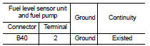
2. Also check harness for short to power.
Is the inspection result normal? YES >> GO TO 9.
NO >> Repair open circuit or short to power in harness or connectors.
9.CHECK FUEL PUMP
Refer to EC-782, "Component Inspection".
Is the inspection result normal? YES >> GO TO 10.
NO >> Replace ŌĆ£fuel level sensor unit and fuel pumpŌĆØ.
10.CHECK INTERMITTENT INCIDENT
Refer to GI-42, "Intermittent Incident".
Is the inspection result normal? YES >> Replace IPDM E/R.
NO >> Repair or replace harness or connectors.
Component Inspection
1.CHECK FUEL PUMP
1. Turn ignition switch OFF.
2. Disconnect ŌĆ£fuel level sensor unit and fuel pumpŌĆØ harness connector.
3. Check resistance between ŌĆ£fuel level sensor unit and fuel pumpŌĆØ terminals as follows.
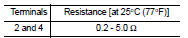
Is the inspection result normal? YES >> INSPECTION END
NO >> Replace ŌĆ£fuel level sensor unit and fuel pumpŌĆØ.
 Fuel injector
Component Function Check
1.INSPECTION START
Turn ignition switch to START.
Is any cylinder ignited?
YES >> GO TO 2.
NO >> Go to EC-778, "Diagnosis Procedure".
2.CHECK ...
 Ignition signal
Component Function Check
1.INSPECTION START
Turn ignition switch OFF, and restart engine.
Does the engine start?
YES-1 >> With CONSULT-III: GO TO 2.
YES-2 >> Without CONSULT-III: ...
Other materials:
Safety note
WARNING
ŌĆó Do not disassemble or modify this system. If you do, it may result in accidents,
fire, or electric shock.
ŌĆó Do not use this system if you notice any abnormality, such as a frozen screen
or lack of sound. Continued use of the system may result in accident, fire or electric
shock ...
Corrosion protection
Most common factors contributing to vehicle corrosion
The persistent accumulation of moisture-retaining dirt, road grime, and organic debris within hidden body panel sections, structural cavities, and hard-to-reach areas of your Nissan Leaf.
Compromised integrity of the facto ...
Heated seats (if so equipped)
WARNING
Do not use or allow occupants to use the seat heater if you or the occupants
cannot monitor elevated seat temperatures or have an inability to feel pain in body
parts that contact the seat. Use of the seat heater by such people could result
in serious injury.
CAUTION
ŌĆó The battery ...
