
Nissan Juke Service and Repair Manual : GPS antenna
Feeder Layout
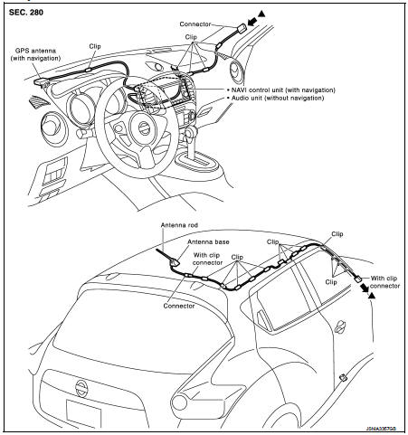
Removal and Installation
REMOVAL
1. Remove instrument panel. Refer to IP-12, "Exploded View".
2. Remove antenna feeder clip, then remove GPS antenna screw and remove GPS antenna.
INSTALLATION
Install in the reverse order of removal.
 Antenna base
Exploded View
1. Antenna rod
2. Antenna base
: N·m (kg-m, in-lb)
Removal and Installation
REMOVAL
1. Remove headlining. Refer to INT-26, "Exploded View".
2. Disconnect antenna fee ...
 Microphone
Removal and Installation
REMOVAL
1. Remove headlining. Refer to INT-26, "Exploded View".
2. Remove microphone connector and pawl to remove microphone.
INSTALLATION
Install in the reve ...
Other materials:
B1080, B1096 driver air bag module
DTC Logic
DTC DETECTION LOGIC
DTC CONFIRMATION PROCEDURE
1.CHECK SELF-DIAG RESULT
With CONSULT-III
1. Turn ignition switch ON.
2. Perform “Self Diagnostic Result� mode of “AIR BAG� using CONSULT-III.
Without CONSULT-III
1. Turn ignition switch ON.
2. Check the air bag warning la ...
Steering switch signal B circuit
Description
Transmits the steering switch signal to NAVI control unit.
Diagnosis Procedure
1.CHECK STEERING SWITCH SIGNAL B CIRCUIT
1. Disconnect NAVI control unit connector and spiral cable connector.
2. Check continuity between NAVI control unit harness connector and spiral cable
harness co ...
Wiring diagram
IPDM E/R
Wiring Diagram
For connector terminal arrangements, harness layouts, and alphabets in a
(option abbreviation; if not
described in wiring diagram), refer to GI-12, "Connector Information/Explanation
of Option Abbreviation".
...
