Nissan Juke Service and Repair Manual : Steering switch signal B circuit
Description
Transmits the steering switch signal to NAVI control unit.
Diagnosis Procedure
1.CHECK STEERING SWITCH SIGNAL B CIRCUIT
1. Disconnect NAVI control unit connector and spiral cable connector.
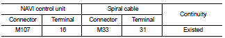
2. Check continuity between NAVI control unit harness connector and spiral cable harness connector.
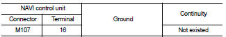
3. Check continuity between NAVI control unit harness connector and ground.
Is the inspection result normal? YES >> GO TO 2.
NO >> Repair harness or connector.
2.CHECK SPIRAL CABLE
Check spiral cable.
Is the inspection result normal? YES >> GO TO 3.
NO >> Replace spiral cable. Refer to SR-16, "Exploded View".
3.CHECK NAVI CONTROL UNIT VOLTAGE
1. Connect NAVI control unit connector and spiral cable connector.
2. Turn ignition switch ON.
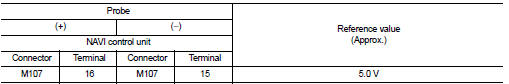
3. Check voltage between NAVI control unit harness connector.
Is the inspection result normal? YES >> GO TO 4.
NO >> Replace NAVI control unit. Refer to AV-84, "Removal and Installation".
4.CHECK STEERING SWITCH
1. Turn ignition switch OFF.
2. Check steering switch. Refer to AV-74, "Component Inspection".
Is the inspection result normal? YES >> INSPECTION END
NO >> Replace steering switch. Refer to AV-91, "Exploded View".
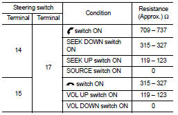
Component Inspection
Measure the resistance between the steering switch connector.
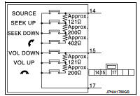
Standard
 Steering switch signal A circuit
Description
Transmits the steering switch signal to NAVI control unit.
Diagnosis Procedure
1.CHECK STEERING SWITCH SIGNAL A CIRCUIT
1. Disconnect NAVI control unit connector and spiral cable conne ...
 Steering switch ground circuit
Description
Transmits the steering switch signal to NAVI control unit.
Diagnosis Procedure
1.CHECK STEERING SWITCH SIGNAL GROUND CIRCUIT
1. Disconnect NAVI control unit connector and spiral cable ...
Other materials:
Warning/Indicator lights (yellow)
or
Anti-lock Braking System (ABS) warning light
When you place the power switch in the ON or "READY to drive" position, the Anti-lock Braking System (ABS) warning light will illuminate briefly and then extinguish. This serves as a standard system self-check to confirm ...
Push-button ignition switch operation
When the ignition switch is pushed without depressing the brake pedal (Continuously
Variable Transmission models) or the clutch pedal (manual transmission models),
the ignition switch position will change as follows: • Push once to change to ACC.
• Push two times to change to ON.
• Pus ...
P0705 transmission range switch A
DTC Logic
DTC DETECTION LOGIC
DTC CONFIRMATION PROCEDURE
CAUTION:
Always drive vehicle at a safe speed.
NOTE:
If “DTC CONFIRMATION PROCEDURE” has been previously performed, always turn
ignition switch
OFF and wait at least 10 seconds before performing the next test.
After the repai ...
