Nissan Juke Service and Repair Manual : P0110 IAT sensor
DTC Logic
DTC DETECTION LOGIC
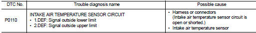
Diagnosis Procedure
1.CHECK GROUND CONNECTIONS
1. Turn ignition switch OFF.
2. Check ground connection E38. Refer to Ground inspection in GI-44, "Circuit Inspection".
Is the inspection result normal? YES >> GO TO 2.
NO >> Repair or replace ground connection.
2.CHECK INTAKE AIR TEMPERATURE SENSOR POWER SUPPLY CIRCUIT-II
1. Disconnect mass air flow sensor (with intake air temperature sensor) harness connector.
2. Turn ignition switch ON.
3. Check the voltage between mass air flow sensor harness connector and ground.
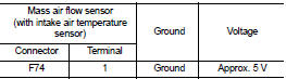
Is the inspection result normal? YES >> GO TO 3.
NO >> Repair open circuit or short to ground or short to power in harness or connectors.
3.CHECK INTAKE AIR TEMPERATURE SENSOR GROUND CIRCUIT FOR OPEN AND SHORT
1. Turn ignition switch OFF.
2. Disconnect ECM harness connector.
3. Check the continuity between mass air flow sensor harness connector and ECM harness connector.
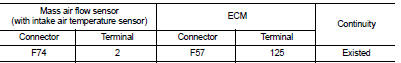
4. Also check harness for short to ground and short to power.
Is the inspection result normal? YES >> GO TO 4.
NO >> Repair open circuit or short to ground or short to power in harness or connectors.
4.CHECK INTAKE AIR TEMPERATURE SENSOR
Refer to EC-906, "Component Inspection".
Is the inspection result normal? YES >> GO TO 5.
NO >> Replace mass air flow sensor (with intake air temperature sensor).
5.CHECK INTERMITTENT INCIDENT
Refer to GI-42, "Intermittent Incident", ???INCIDENT SIMULATION TESTS??? and ???GROUND INSPECTION???.
>> INSPECTION END
Component Inspection
1.CHECK INTAKE AIR TEMPERATURE SENSOR
Check resistance between mass air flow sensor terminals 1 and 2 under the following conditions.
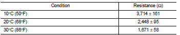
Is the inspection result normal? YES >> INSPECTION END
NO >> Replace mass air flow sensor (with intake air temperature sensor).
 P0101 MAF sensor
DTC Logic
DTC DETECTION LOGIC
Diagnosis Procedure
1.CHECK AIR FILTER
Check that air filter is not obstructed.
Is the inspection result normal?
Yes >> Repair or replace.
No >> ...
 P0115 ECT sensor
DTC Logic
DTC DETECTION LOGIC
Diagnosis Procedure
1.CHECK GROUND CONNECTIONS
1. Turn ignition switch OFF.
2. Check ground connection E38. Refer to Ground inspection in GI-44, "Circuit
In ...
Other materials:
U1000 can comm circuit
Description
CAN (Controller Area Network) is a serial communication line for real time
applications. It is an on-vehicle multiplex
communication line with high data communication speed and excellent error
detection ability. Modern
vehicle is equipped with many electronic control unit, and eac ...
Lights
Headlight assembly
Map light
Room light
High-mounted stop light
Rear combination light
Door mirror turn signal light (if so equipped)
Cargo light
License plate light
Fog light (if so equipped)
...
Direct injection gasoline system
Direct injection gasoline system : System Diagram
Direct injection gasoline system : System Description
INPUT/OUTPUT SIGNAL CHART
*1: This sensor is not used to control the engine system under normal
conditions.
*2: CVT models
*3: M/T models
*4: ECM determines the start signal status by ...
