Nissan Juke Service and Repair Manual : Back door opener system
System Diagram
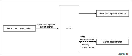
System Description
BACK DOOR OPENER OPERATION
When back door opener switch is pressed, BCM operates back door opener actuator.
NOTE
:
Back door opener actuator is not for locking the back door. The function is only
to open the back door.
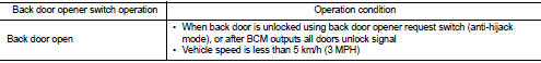
OPERATION CONDITION
If the following conditions are satisfied, back door opener operation is performed.
NOTE
:
ŌĆó When battery terminal is disconnected and reconnected during all doors unlock
state, back door may not
open.
ŌĆó Regardless of door lock actuator state, BCM resets recognition of all doors unlock state approximately 30 seconds after battery terminal is disconnected and BCM recognizes that all doors are in lock state.
ŌĆó When battery terminal is reconnected and back door does not open, have BCM recognize that all doors are in unlock state.
 Remote keyless entry system
Remote keyless entry function
REMOTE KEYLESS ENTRY FUNCTION : System Diagram
REMOTE KEYLESS ENTRY FUNCTION : System Description
DOOR LOCK AND UNLOCK OPERATION
ŌĆó When door lock and unlock butto ...
 Diagnosis system (BCM)
Common item
COMMON ITEM : CONSULT-III Function (BCM - COMMON ITEM)
APPLICATION ITEM
CONSULT-III performs the following functions via CAN communication with BCM.
SYSTEM APPLICATION
BCM can perfo ...
Other materials:
Auto door lock operation does not operate
Diagnosis Procedure
1.CHECK ŌĆ£AUTO LOCK SETŌĆØ SETTING IN ŌĆ£WORK SUPPORTŌĆØ
1. Select ŌĆ£INTELLIGENT KEYŌĆØ of ŌĆ£BCMŌĆØ using CONSULT-III.
2. Select ŌĆ£AUTO LOCK SETŌĆØ in ŌĆ£WORK SUPPORTŌĆØ mode.
3. Check ŌĆ£AUTO LOCK SETŌĆØ in ŌĆ£WORK SUPPORTŌĆØ.
Refer to DLK-43, "INTELLIGENT KEY : ...
CSC (concentric slave cylinder)
Exploded View
1. Transaxle assembly
2. CSC (Concentric Slave Cylinder)
: Always replace after every
disassembly.
: N┬Ęm (kg-m, ft-lb)
Removal and Installation
CAUTION:
ŌĆó Never reuse CSC (Concentric Slave Cylinder). Because CSC slides back to the
original position
every time when rem ...
Rear seats
Folding
Before folding the rear seats:
Secure the seat belts on the seat belt hooks on the side wall. (See ŌĆ£Seat belt
hooksŌĆØ .) To fold the seatback, pull the adjusting knob1 .
To return the seatback to the seating position, lift up each seatback and push
it to the upright position unti ...
