Nissan Juke Service and Repair Manual : Remote keyless entry system
Remote keyless entry function
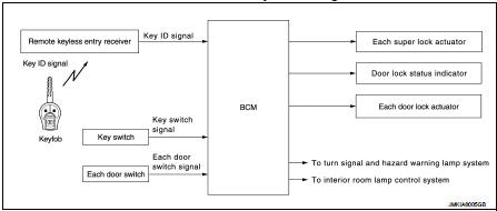
REMOTE KEYLESS ENTRY FUNCTION : System Diagram
REMOTE KEYLESS ENTRY FUNCTION : System Description
DOOR LOCK AND UNLOCK OPERATION
ŌĆó When door lock and unlock button of keyfob is pressed, door lock and unlock signal transmits from keyfob to BCM via remote keyless entry receiver.
ŌĆó When BCM receives the door lock and unlock signal, it operates door lock actuator, blinks the hazard lamp at the same time as a reminder.
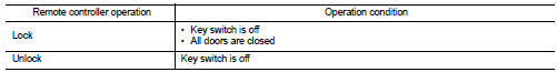
OPERATION CONDITION
If the following conditions are satisfied, door lock/unlock operation is performed if the keyfob is operated.
OPERATION AREA
To ensure that the keyfob works effectively, use within 100 cm (3 ft) range of each door, however the operable range may differ according to surroundings.
ANTI-HIJACK FUNCTION
Information of super lock function with anti-hijack function.
Refer to DLK-367, "SUPER LOCK FUNCTION : System Description".
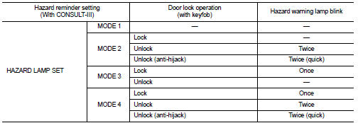
HAZARD REMINDER OPERATION
When door is locked or unlocked by keyfob, then BCM blinks hazard warning lamp as a reminder.
NOTE
:
Hazard reminder mode can be changed with CONSULT-III. Refer to DLK-372, "MULTI
REMOTE ENT : CONSULT-
III Function (BCM - MULTI REMOTE ENT) (With Super Lock)".
AUTO DOOR LOCK FUNCTION
After door is unlocked by keyfob button operation and if 30 seconds or more passes without performing the following operation, all doors are automatically locked. However, operation check function does not activate.

Auto door lock mode can be changed by the ŌĆ£AUTO LOCK SETŌĆØ mode in ŌĆ£WORK SUPPORTŌĆØ. Refer to DLK- 371, "DOOR LOCK : CONSULT-III Function (BCM - DOOR LOCK) (With Super Lock)".
INTERIOR ROOM LAMP CONTROL FUNCTION
Interior room lamp is controlled according to door lock/unlock state, refer to INL-6, "INTERIOR ROOM LAMP CONTROL SYSTEM : System Description".
Super lock function
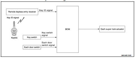
SUPER LOCK FUNCTION : System Diagram
SUPER LOCK FUNCTION : System Description
ŌĆó Super lock provides a higher anti-theft performance than a conventional door lock function.
ŌĆó BCM controls the super lock system.
ŌĆó When all doors are closed super lock system can be set/release by keyfob.
ŌĆó When super lock is set, inside handle of doors do not work.
SUPER LOCK SET OPERATION (LOCK OPERATION)
When Keyfob lock button is operated while all doors are in unlock state, super lock of all doors is set, and simultaneously, all doors are locked.
SUPER LOCK RELEASE OPERATION (UNLOCK OERATION) WITH ANTI-HIJACK MODE
When Keyfob unlock button is operated while super lock of all doors is set, super lock of all doors is released, and simultaneously, driver door are unlocked. When Keyfob unlock button is operated again, all doors are unlocked.
SUPER LOCK RELEASE OPERATION (UNLOCK OERATION) WITHOUT ANTI-HIJACK MODE
When keyfob unlock button is operated while super lock of all doors is set, super lock of all doors is released, and simultaneously, all doors are unlocked.
ANTI-HIJACK FUNCTION SETTING
 With CONSULT-III
Refer to DLK-371, "DOOR LOCK : CONSULT-III Function (BCM - DOOR LOCK) (With Super Lock)".
 Without CONSULT-III
ŌĆó ON/OFF can be switched when keyfob lock button and unlock button are pressed simultaneously for 4 seconds or more while steering lock is locked.
ŌĆó When mode is switched, hazard warning lamp blinks.
OFF → ON : 1 blinks ON → OFF : 3 blink
 Power door lock system
System Diagram
System Description
DOOR LOCK FUNCTION
ŌĆó The door lock and unlock switch (driver side) is build into power window
main switch.
ŌĆó The door lock and unlock switch (passenger si ...
 Back door opener system
System Diagram
System Description
BACK DOOR OPENER OPERATION
When back door opener switch is pressed, BCM operates back door opener
actuator.
NOTE:
Back door opener actuator is not for lock ...
Other materials:
P1572 ASCD brake switch
DTC Logic
DTC DETECTION LOGIC
NOTE:
ŌĆó If DTC P1572 is displayed with DTC P0605, first perform the trouble diagnosis
for DTC P0605. Refer
to EC-302, "DTC Logic".
ŌĆó This self-diagnosis has the one trip detection logic. When malfunction A is
detected, DTC is not
stored in ECM me ...
Precaution
Precaution for Supplemental Restraint System (SRS) "AIR BAG" and "SEAT
BELT
PRE-TENSIONER"
The Supplemental Restraint System such as ŌĆ£AIR BAGŌĆØ and ŌĆ£SEAT BELT PRE-TENSIONERŌĆØ,
used along
with a front seat belt, helps to reduce the risk or severity of injury to the
...
Ecu diagnosis information
AUDIO UNIT
Reference Value
TERMINAL LAYOUT
PHYSICAL VALUES
ŌĆó *1: Models with USB connection function
ŌĆó *2: Models without USB connection function ...
