Nissan Juke Service and Repair Manual : Rocker cover
Exploded View
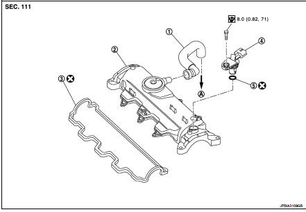
1. Blow-by hose
2. Rocker cover
3. Gasket
4. Camshaft position sensor
5. O-ring
A. To turbocharger air inlet pipe
 : N·m (kg-m, in-lb)
 : Always replace after every
disassembly.
Removal and Installation
REMOVAL
1. Remove air cleaner case. Refer to EM-280, "Exploded View".
2. Remove inlet pipe assembly and air inlet tube. Refer to EM-281, "Exploded View".
3. Remove high pressure protection cover (upper). Refer to EM-294, "Exploded View".
4. Remove electric throttle control actuator.
5. Remove fuel injector. Refer to EM-294, "Exploded View".
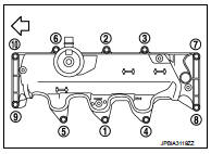
6. Remove rocker cover.
• Loosen holding bolts in the reverse order as shown in the figure and remove.
 : Engine front
INSTALLATION
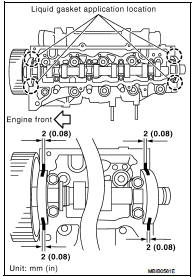
1. Apply liquid gasket on locations shown in the figure.
• Use Genuine Liquid gasket or equivalent.
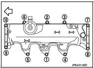
2. Tighten holding bolts in the numerical order as shown in the figure.
: Engine front
 : 12 N·m (1.2 kg-m, 9 ft-lb)
3. Install in the reverse order of removal after this steps.
 High pressure supply pump
Exploded View
1. High pressure supply pump protector
2. High pressure supply pump
: N·m (kg-m, ft-lb)
Removal and Installation
REMOVAL
CAUTION:
• Be sure to read “Precautions for Diesel ...
 Timing belt
Exploded View
1. Timing belt inner cover
2. Timing belt
3. Camshaft sprocket
4. Timing belt tensioner
5. Timing belt upper cover
6. Timing belt lower cover
7. Cylinder head suspended brac ...
Other materials:
Compressor dose dot operate
Description
SYMPTOM
Compressor dose not operate.
Diagnosis Procedure
NOTE:
• Perform self-diagnosis with CONSULT-III before performing symptom diagnosis.
If any malfunction result or
DTC is detected, perform the corresponding diagnosis.
• Check that refrigerant is enclosed in cooler cyc ...
B2098 ignition relay on stuck
Description
• IPDM E/R operates the ignition relay when it receives an ignition switch ON
signal from BCM via CAN communication.
• Turn the ignition relay OFF by pressing the push-button ignition switch once
when the vehicle speed is 4 km/
h (2.5 MPH) or less.
• Turn the ignition relay ...
B1058, B1059, B1060, B1061, B1062, B1063 diagnosis sensor unit
DTC Logic
DTC DETECTION LOGIC
DTC CONFIRMATION PROCEDURE
1.CHECK SELF-DIAG RESULT
With CONSULT-III
1. Turn ignition switch ON.
2. Perform “Self Diagnostic Result” mode of “AIR BAG” using CONSULT-III.
Without CONSULT-III
1. Turn ignition switch ON.
2. Check the air bag warning la ...
