Nissan Juke Service and Repair Manual : Timing belt
Exploded View
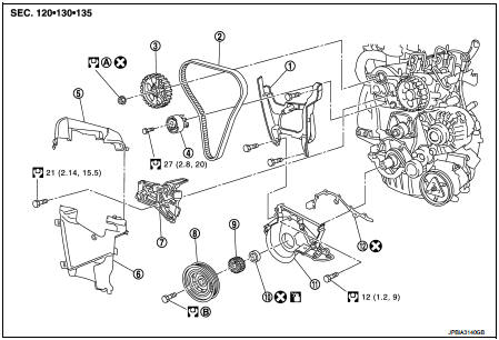
1. Timing belt inner cover
2. Timing belt
3. Camshaft sprocket
4. Timing belt tensioner
5. Timing belt upper cover
6. Timing belt lower cover
7. Cylinder head suspended bracket
8. Crankshaft pulley
9. Crankshaft sprocket
10. Rear oil seal
11. Rear oil seal retainer
12. Gasket
A Refer to EM-311
B Refer to EM-302
 : N·m (kg-m, ft-lb)
 : Always replace after every
disassembly.
 : Should be lubricated with oil.
Removal and Installation
CAUTION:
• Apply new engine oil to parts marked in illustration before installation.
• Replace any belt that has been removed.
• Never turn the engine in the direction opposite to that of normal operation.
• When replacing the timing belt, be sure to replace the timing belt tensioner.
• Never run the engine without the drive belts to avoid damaging the crankshaft pulley.
REMOVAL
1. Disconnect battery cable from the negative terminal.
2. Remove engine under cover.
3. Remove front wheel RH.
4. Remove fender protector RH. Refer to EXT-22, "Exploded View" 5. Remove drive belt, and auto-tensioner. Refer to EM-276, "Removal and Installation".
6. Remove RH engine torque rod.
7. Remove RH engine mounting.
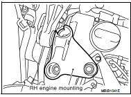
8. Remove RH engine mounting support bracket and RH engine mounting insulator.
9. Remove upper timing cover, camshaft position sensor and cylinder head suspended mounting bracket.
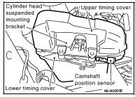
10. Remove timing belt lower cover.10. Remove timing belt lower cover.
11. Remove the TDC pin bolt.
11. Remove the TDC pin bolt.
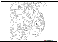
12. Rotate the crankshaft clockwise, until the position (A) of the camshaft pulley becomes opposite of the position (B) on the cylinder head.
![13. Insert TDC set pin [SST: KV113B0110 (Mot. 1430)] (A) into the](images/books/335/6/index.139.jpg)
13. Insert TDC set pin [SST: KV113B0110 (Mot. 1430)] (A) into the camshaft pulley and cylinder head hole.

14. Screw in the TDC pin (special service tool).

15. Turn the engine clockwise (timing side) until the crankshaft reaches the TDC pin (special service tool).
![16. The pin [SST: KV113B0110 (Mot. 1430)] (A) must engage in the](images/books/335/7/index.14.gif)
16. The pin [SST: KV113B0110 (Mot. 1430)] (A) must engage in the camshaft pulley and cylinder head holes.

17. Insert flat-bladed screwdriver into the place of crankshaft position sensor to block crankshaft and loosen crankshaft pulley bolt (1).
18. Remove crankshaft pulley.
CAUTION:
Never remove fixing bolts. Keep loosened fixing bolts in
place to protect removed crankshaft pulley from dropping.
19. Slacken the timing belt by loosening the bolt of tensioner (1), then remove timing belt.

INSTALLATION
Install in the reverse order of removal paying attention to the following.
TIMING ADJUSTMENT
CAUTION:
It is essential to degrease the end of the crankshaft, the bore of the
crankshaft sprocket and the bearing
faces of the drive belt pulley to prevent any slip between the timing and the
crankshaft which
would risk destroying the engine.
1. Install timing belt tensioner.
NOTE
:
Put the timing belt tensioner spigot (1) in the cylinder head
groove.
2. Insert Tool KV113B0110 (Mot. 1430) (A) in the camshaft pulley and cylinder head holes.
3. Check that the mark on the high pressure pump pulley (2) has shifted one tooth to the right of vertical axle.

4. Turn crankshaft to set Tool KV113B0130 (Mot. 1489) (the crankshaft groove (1) must be facing upwards).

5. Tighten old crankshaft pulley bolt with a spacer (1) (which does not cover the timing sprocket mark).

6. Insert tool KV113B0130 (Mot. 1489) to crankshaft.
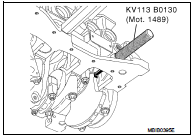
7. Remove one wheel bolt from crankshaft pulley, and then loosen the other two bolts (1).

8. Install the timing belt, aligning the marks on the belt with those on the camshaft and fuel injection pump sprockets (19 teeth spaces on the belt between the marks on the camshaft and pump sprockets).
9. Using a 6 mm (0.24 in) Allen key, move the movable index (F) of the tension wheel into the position shown below, by turning the key counterclockwise.

10. Tighten the tension wheel bolt.
 : 27 N·m (2.8 kg-m, 20 ft-lb)
11. Check that the camshaft pulley wheel bolts are not fully up against the camshaft pulley wheel.
12. Install and tighten camshaft pulley wheel bolt.
 : 14 N·m (1.4 kg-m, 10 ft-lb)
13. Remove Tool KV113B0130 (Mot. 1489) and Tool KV113B0110 (Mot. 1430).
14. Turn the crankshaft two full turns in a clockwise direction (timing side). Just before the hole (A) of the camshaft pulley is opposite the cylinder head hole (B), insert tool KV113B0130 (Mot. 1489) into the cylinder block.
15. Then turn the crankshaft slowly and smoothly against TDC set pin.
![16. Insert TDC set pin [SST: KV113B0110 (Mot. 1430)] (A).](images/books/335/7/index.25.jpg)
16. Insert TDC set pin [SST: KV113B0110 (Mot. 1430)] (A).
If the pin cannot be inserted, perform the following.
a. Remove TDC set pin [SST: KV113B0130 (Mot. 1489)].
b. Loosen camshaft pulley wheel bolts.
c. Turn camshaft pulley to adjust.
d. Confirm that the crankshaft sprocket groove is facing upward.
e. Loosen timing belt tensioner bolt.

f. Move the movable index of the drive belt tensioner into the position as shown in the figure, by turning the key clockwise.
g. Tighten timing belt tensioner bolt.
: 27 N·m (2.8 kg-m, 20 ft-lb)
h. Install and tighten camshaft sprocket wheel bolts.
 : 14 N·m (1.4 kg-m, 10 ft-lb)

i. Turn the crankshaft two revolutions in a clockwise direction (timing side). Just before the hole (A) of the camshaft pulley is opposite the cylinder head hole (B), insert TDC set pin [SST: KV113B0130 (Mot. 1489)] into the cylinder block.
j. Then turn the crankshaft slowly and smoothly against TDC set pin.

17. Install crankshaft pulley (1), and tighten the bolts as follows: a. Tighten the bolt.
 120 N·m (12 kg-m, 89 ft-lb)
b. Turn the bolt 95 degrees ±15 degrees clockwise (angle tightening).
![18. Remove TDC set pin [SST: KV113B0130 (Mot. 1489)] and TDC set pin [SST:](images/books/335/7/index.29.jpg)
18. Remove TDC set pin [SST: KV113B0130 (Mot. 1489)] and TDC set pin [SST: KV113B0110 (Mot. 1430)].
19. Apply liquid gasket to the thread of TDC pin plug.
20. Install TDC pin plug.
 : 20 N·m (2.0 kg-m, 15 ft-lb)
21. Install the cylinder head suspended bracket.
 : 21 N·m (2.1 kg-m, 15 ft-lb)

22. Install the lower timing cover by positioning the tab (M) into the hole (N) on the inner timing cover.


23. Install the upper timing cover.

24. Install the water pipe.
 : 22 N·m (2.2 kg-m, 16 ft-lb)
25. Install the two water hoses.
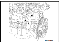
26. Install the alternator bracket.
 : 44 N·m (4.5 kg-m, 32 ft-lb)
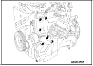
27. Install the alternator.
Engine number Tightening torque < D051474 : 21 N·m (2.1 kg-m, 15 ft-lb) >≥≥ : 25 N·m (2.6 kg-m, 18 ft-lb)
28. Install the A/C compressor.
 : 21 N·m (2.1 kg-m, 15 ft-lb)
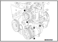
29. Install the power steering pump or the washer which replaces the pulley (if the engine has one).
 : 21 N·m (2.1 kg-m, 15 ft-lb)

30. Install the drive belt.
CAUTION:
• Make sure belt is correctly engaged with the pulley
groove.
• Check for oil and coolant on belt and each pulley groove.
• Certain drive belts have five teeth whereas the air conditioning compressor pulley, power-assisted steering pump pulley, and alternator pulley all have six teeth. In this case, it is essential to check that the inner tooth (O) of the pulleys remains free when fitting the drive belt.
Never turn the engine in the opposite direction to its normal operating direction.
Use a brush to remove any deposits from the crankshaft pulley V grooves.
For engines fitted with a mechanical tensioning roller, it is essential to replace the tensioning roller mounting bolts.
31. Make sure that tension of each belt is within the standard.
 Rocker cover
Exploded View
1. Blow-by hose
2. Rocker cover
3. Gasket
4. Camshaft position sensor
5. O-ring
A. To turbocharger air inlet pipe
: N·m (kg-m, in-lb)
: Always replace after every
disassem ...
 Cylinder head
Exploded View
1. Camshaft sprocket
2. Cylinder head suspended bracket
3. Valve lifter
4. Valve rotator
5. Valve spring retainer
6. Valve spring
7. Exhaust valve
8. Intake valve
9. Val ...
Other materials:
Auto door lock operation does not operate
Diagnosis Procedure
1.CHECK “AUTO LOCK SET” SETTING IN “WORK SUPPORT”
1. Select “INTELLIGENT KEY” of “BCM” using CONSULT-III.
2. Select “AUTO LOCK SET” in “WORK SUPPORT” mode.
3. Check “AUTO LOCK SET” in “WORK SUPPORT”.
Refer to DLK-43, "INTELLIGENT KEY : CONSULT-III Function (BCM - INTE ...
P0132 A/F sensor 1
DTC Logic
DTC DETECTION LOGIC
To judge the malfunction, the diagnosis checks that the A/F signal computed
by ECM from the A/F sensor 1
signal is not inordinately high.
DTC CONFIRMATION PROCEDURE
1.PRECONDITIONING
If DTC Confirmation Procedure has been previously conducted, always turn
ig ...
Combination switch output circuit
Diagnosis Procedure
1.CHECK OUTPUT 1 - 5 CIRCUIT FOR OPEN
1. Turn ignition switch OFF.
2. Disconnect BCM and combination switch connectors.
3. Check continuity between BCM harness connector and combination switch harness
connector.
Does continuity exist?
YES >> GO TO 2.
NO >> ...
