Nissan Juke Service and Repair Manual : Removal and installation
Exhaust system
Exploded View
2WD
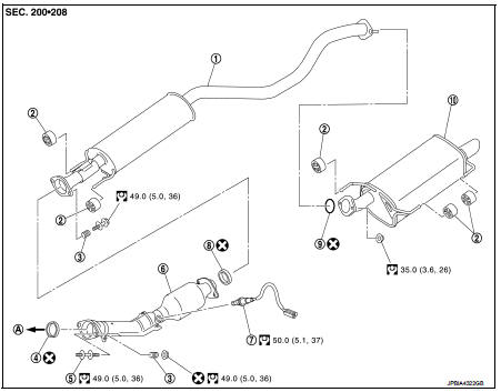
1. Center muffler
2. Mounting rubber
3. Spring
4. Seal bearing
5. Stud bolt
6. Three way catalyst
7. Heated oxygen sensor 2
8. Seal bearing
9. Ring gasket
10. Main muffler
A. To catalyst convertor
 : N·m (kg-m, ft-lb)
 : Always replace after every
disassembly.
4WD
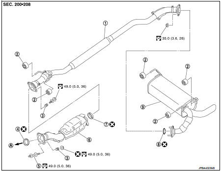
1. Center pipe
2. Mounting rubber
3. Spring
4. Seal bearing
5. Stud bolt
6. Three way catalyst
7. Seal bearing
8. Ring gasket
9. Main muffler
A. To catalyst convertor
 : N·m (kg-m, ft-lb)
 : Always replace after every
disassembly.
Removal and Installation
REMOVAL
• Disconnect each joint and mounting.
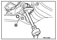
• Remove heated oxygen sensor 2 with following procedure: - Using heated oxygen sensor wrench [SST: KV10114400] (A), removal heated oxygen sensor 2 (1).
2 : Exhaust front tube
CAUTION:
Be careful not to damage heated oxygen sensor 2.
INSTALLATION
Note the following, and install in the reverse order of removal.
CAUTION:
• Always replace seal bearings with new ones when reassembling.
• Discard any heated oxygen sensor 2 which has been dropped onto a hard surface such as a concrete floor. Use a new one.
• Before installing a new heated oxygen sensor 2, clean exhaust system threads using the heated oxygen sensor thread cleaner [commercial service tool: J-43897-18 or J-43897-12] and apply anti-seize lubricant (commercial service tool).
• Never over torque heated oxygen sensor 2. Doing so may cause damage to the heated oxygen sensor 2, resulting in the “MIL” coming on.
• If heat insulator is badly deformed, repair or replace it. If deposits such as mud pile up on the heat insulator, remove them.
• When installing heat insulator avoid large gaps or interference between heat insulator and each exhaust pipe.
• Remove deposits from the sealing surface of each connection. Connect them securely to avoid gas leakage.
• When installing each mounting rubber, use silicon oil to avoid twisting.
• Temporarily tighten mounting nuts and bolts. Check each part for unusual interference and mounting rubber interference, and then tighten them to the specified torque.
• When installing each mounting rubber, avoid twisting or unusual extension in up/down, front/rear and right/left directions.
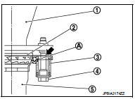
Catalyst convertor to Exhaust Front Tube 1. Securely insert seal bearing (2) into catalyst convertor (1).
3 : Spring
4 : Nut
5 : Exhaust front tube
CAUTION:
Be careful not to damage seal bearing surface when installing.
2. With spring, tighten nut.
CAUTION:
• Fasten stud bolts to the flange of exhaust manifold side to
the specified torque before fastening mounting nuts.
• Ensure springs are seated correctly on the flange and not sitting on (A).
• Be careful that stud bolt does not interfere with mounting hole of exhaust
front tube ( ).
).
3. After installing, check that stud bolt does not interfere with mounting hole of exhaust front tube.
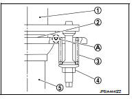
Exhaust Front Tube to Center Muffler 1. Securely insert seal bearing (2) into exhaust front tube (1) side in the direction shown in the figure.
3 : Spring
4 : Bolt
5 : Center muffler
CAUTION:
Be careful not to damage seal bearing surface when installing.
2. With spring, tighten bolt.
CAUTION:
• Ensure springs are seated correctly on the flange and not sitting on (A).
• Be careful that bolt does not interfere with mounting hole of center muffler (
).
3. After installing, check that bolt does not interfere with mounting hole of center muffler.
Inspection
INSPECTION AFTER INSTALLATION
• Check clearance between tail tube and rear bumper is even.
• With engine running, check exhaust tube joints for gas leakage and unusual noises.
• Check to ensure that mounting brackets and mounting rubbers are installed properly and free from undue stress. Improper installation could result in excessive noise and vibration.
 Periodic maintenance
EXHAUST SYSTEM
Inspection
Check exhaust pipes, muffler, and mounting for improper attachment,
leakage, cracks, damage or deterioration.
• If anything is found, repair or replace damaged parts. ...

Other materials:
Steering switch ground circuit
Description
Transmits the steering switch signal to audio unit.
Diagnosis Procedure
1.CHECK STEERING SWITCH SIGNAL GROUND CIRCUIT
1. Disconnect audio unit connector and spiral cable connector.
2. Check continuity between audio unit harness connector and spiral cable
harness connector.
Is t ...
Multiport Fuel Injection System or Engine Control System
• Before connecting or disconnecting any harness connector for the
multiport fuel injection system or ECM:
Turn ignition switch to “OFF” position.
Disconnect negative battery terminal. Otherwise, there may be damage to ECM.
• Before disconnecting pressurized fuel line from fuel pump to ...
Instrument Panel
Vents: Adjustable climate control outlets for personalized cabin airflow.
Meters and gauges: Comprehensive digital driver information display providing real-time vehicle data.
Center multi-function control panel*: Central hub for infotainment, connec ...
