Nissan Juke Service and Repair Manual : Key switch
Component Function Check
1.CHECK FUNCTION
1. Select ÔÇťDOOR LOCKÔÇŁ of ÔÇťBCMÔÇŁ using CONSULT-III.
2. Select ÔÇťKEY ON SWÔÇŁ in ÔÇťDATA MONITORÔÇŁ mode.
3. Check that the function operates normally according to the following conditions.
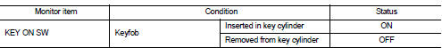
Is the inspection result normal? YES >> Key switch is OK.
NO >> Refer to DLK-401, "Diagnosis Procedure".
Diagnosis Procedure
1.CHECK FUSE
1. Turn ignition switch OFF.
2. Check 10 A fuse, [No.7, located in fuse block (J/B)].
Is fuse fusing? YES >> Replace the blown fuse after repairing the affected circuit if a fuse is blown.
NO >> GO TO 2.
2.CHECK KEY SWITCH POWER SUPPLY CIRCUIT
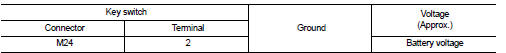
Is the inspection result normal? YES >> GO TO 3.
NO >> Repair or replace harness.
3.CHECK KEY SWITCH CIRCUIT
1. Disconnect BCM connector.
2. Check continuity between key switch harness connector and BCM harness connector.
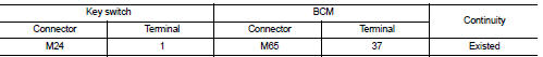
3. Check continuity between key switch connector and ground.
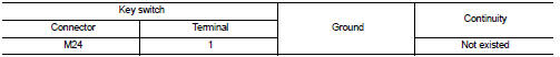
Is the inspection result normal? YES >> GO TO 4 NO >> Repair or replace harness.
4.CHECK KEY SWITCH
Refer to DLK-402, "Component Inspection".
Is the inspection result normal? YES >> GO TO 5.
NO >> Replace key switch.
5.CHECK INTERMITTENT INCIDENT
Refer to GI-42, "Intermittent Incident".
>> INSPECTION END
Component Inspection
COMPONENT INSPECTION
1.CHECK KEY SWITCH
1. Turn ignition switch OFF.
2. Disconnect key switch connector.
3. Check continuity between key switch terminals.
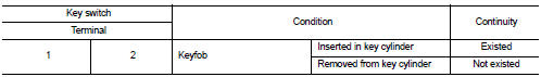
Is the inspection result normal? YES >> INSPECTION END
NO >> Replace key switch.
 Hazard function
Component Function Check
1.CHECK FUNCTION
1. Select ÔÇťMULTI REMOTE ENTÔÇŁ of ÔÇťBCMÔÇŁ using CONSULT-III.
2. Select ÔÇťFLASHERÔÇŁ in ÔÇťACTIVE TESTÔÇŁ mode.
3. Check that the function operates no ...
 Keyfob battery
Component Function Check
1.CHECK FUNCTION
Check door lock and unlock operation with keyfob button.
Is the inspection result normal?
YES >> Keyfob is OK.
NO >> Refer to DLK-403, &q ...
Other materials:
Diagnosis system (BCM) (with intelligent key system)
Description
Air conditioning system performs self-diagnosis, operation check, function
diagnosis, and various settings
using diagnosis function of each control unit.
Common item : consult-III Function (BCM - COMMON ITEM)
APPLICATION ITEM
CONSULT-III performs the following functions via CAN ...
I-LI system limitations
WARNING
The following points outline the critical operational boundaries and inherent limitations of the Intelligent Lane Intervention (I-LI) system. Failure to adhere strictly to these warnings and instructions regarding the proper and safe use of the I-LI system could lead to an unpredictable ...
Turbocharger boost control
Turbocharger boost control : SystemDiagram
Turbocharger boost control : System Description
INPUT/OUTPUT SIGNAL CHART
SYSTEM DESCRIPTION
Depending on driving conditions, the ECM performs ON/OFF duty control of the
turbocharger boost control
solenoid valve and controls the boost by adjustin ...
