Nissan Juke Service and Repair Manual : P0525 ASCD system
DTC Logic
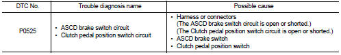
DTC DETECTION LOGIC
Diagnosis Procedure
1.CHECK GROUND CONNECTIONS
1. Turn ignition switch OFF and wait at least 20 seconds.
2. Check ground connection E38. Refer to Ground inspection in GI-44, "Circuit Inspection".
Is the inspection result normal? YES >> GO TO 2.
NO >> Repair or replace ground connection.
2.CHECK ASCD BRAKE SWITCH AND CLUTCH PEDAL POSITION SWITCH POWER SUPPLY CIRCUIT
1. Disconnect ACSD brake switch and clutch pedal position switch harness connectors.
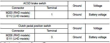
2. Check the voltage between ACSD brake switch and clutch pedal position switch harness connectors and ground.
Is the inspection result normal? YES >> GO TO 3.
NO >> Repair open circuit or short to ground or short to power in harness or connectors.
3.CHECK ASCD BRAKE SWITCH INPUT SIGNAL CIRCUIT AND CLUTCH PEDAL POSITION SWITCH GROUND CIRCUIT FOR OPEN AND SHORT
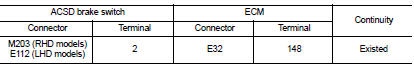
1. Check the continuity between ACSD brake switch harness connector and ECM harness connector.
2. Check the continuity between clutch pedal position switch harness connector and ground.

3. Also check harness for short to ground and short to power.
Is the inspection result normal? YES >> GO TO 4.
NO >> Repair open circuit or short to ground or short to power in harness or connectors.
4.CHECK ASCD BRAKE SWITCH AND CLUTCH PEDAL POSITION SWITCH
Refer to EC-959, "Component Inspection".
Is the inspection result normal? YES >> GO TO 5.
NO >> Replace ASCD brake switch or clutch pedal position switch.
5.CHECK INTERMITTENT INCIDENT
Refer to GI-42, "Intermittent Incident".
Is the inspection result normal? YES >> Replace ACSD brake switch or clutch pedal position switch.
NO >> Repair or replace.
Component Inspection
1.CHECK ASCD BRAKE SWITCH-I
1. Turn ignition switch OFF.
2. Disconnect ASCD brake switch harness connector.
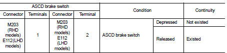
3. Check the continuity between ASCD brake switch terminals under the following condition.
Is the inspection result normal? YES >> GO TO 2.
NO >> Replace ASCD brake switch.
2.CHECK CLUTCH PEDAL POSITION SWITCH-I
1. Turn ignition switch OFF.
2. Disconnect clutch pedal position switch harness connector.
3. Check the continuity between clutch pedal position switch terminals under the following condition.
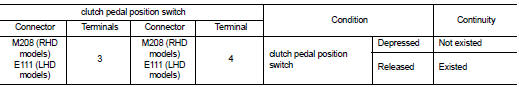
the inspection result normal? YES >> INSPECTION END
NO >> Replace clutch pedal position switch.
 P0504 ASCD brake SWI
DTC Logic
DTC DETECTION LOGIC
Diagnosis Procedure
1.CHECK GROUND CONNECTIONS
1. Turn ignition switch OFF and wait at least 20 seconds.
2. Check ground connection E38. Refer to Ground inspection ...
 P0530 refrigerant pressure sensor
DTC Logic
DTC DETECTION LOGIC
Diagnosis Procedure
1.CHECK GROUND CONNECTIONS
1. Turn ignition switch OFF.
2. Check ground connection E38. Refer to Ground inspection in GI-44, "Circuit
In ...
Other materials:
Special Service Tool
HFC-134a (R-134a) Service Tool and Equipment
ŌĆó Never mix HFC-134a (R-134a) refrigerant and/or its specified lubricant with
CFC-12 (R-12) refrigerant and/
or its lubricant.
ŌĆó Separate and non-interchangeable service equipment must be used for handling
each type of refrigerant/
lubricant.
...
Performance test
Inspection
INSPECTION PROCEDURE
1. Connect recovery/recycling/recharging equipment (for HFC-134a) or manifold
gauge.
2. Start the engine, and set to the following condition.
Test condition
3. Maintain test condition until A/C system becomes stable. (Approximately 10
minutes)
4. Check t ...
General Precautions
WARNING:
When replacing fuel line parts, be sure to observe the following.
ŌĆó Put a ŌĆ£CAUTION: FLAMMABLEŌĆØ sign in the workshop.
ŌĆó Be sure to work in a well ventilated area and furnish workshop with a CO2 fire
extinguisher.
ŌĆó Never smoke while servicing fuel system. Keep open flames a ...
