Nissan Juke Service and Repair Manual : Power supply and ground circuit
Power window main switch
POWER WINDOW MAIN SWITCH : Diagnosis Procedure
1.CHECK POWER WINDOW MAIN SWITCH POWER SUPPLY
1. Turn ignition OFF.
2. Disconnect power window main switch connector.
3. Check voltage between power window main switch harness connector and ground.
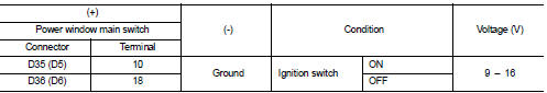
(): RHD models
Is the inspection result normal? YES >> GO TO 3.
NO >> GO TO 2.
2.CHECK POWER WINDOW MAIN SWITCH POWER SUPPLY CIRCUIT
1. Turn ignition switch OFF.
2. Disconnect BCM connector.
3. Check continuity between BCM harness connector and power window main switch harness connector.
[With Intelligent Key
![[Without Intelligent Key]](images/books/335/51/6.html102.jpg)
[Without Intelligent Key]
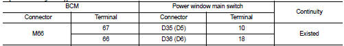
(): RHD models
4. Check continuity between BCM harness connector and ground.
[With Intelligent Key]
![[Without Intelligent Key]](images/books/335/51/6.html104.jpg)
[Without Intelligent Key]
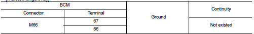
Is the inspection result normal?
YES >> Replace BCM. Refer to BCS-93, "Removal and Installation" (with Intelligent Key) or BCS-161, "Removal and Installation" (without Intelligent Key).
NO >> Repair or replace harness.
3.CHECK POWER WINDOW MAIN SWITCH GROUND CIRCUIT
1. Turn ignition switch OFF.
2. Check continuity between power window main switch harness connector and ground.
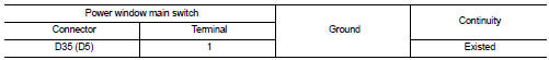
(): RHD models
Is the inspection result normal? YES >> INSPECTION END
NO >> Repair or replace harness.
Front power window switch (passenger side)
FRONT POWER WINDOW SWITCH (PASSENGER SIDE) : Diagnosis Procedure
1.CHECK FRONT POWER WINDOW SWITCH (PASSENGER SIDE) POWER SUPPLY
1. Turn ignition switch OFF.
2. Disconnect front power window switch (passenger side) connector.
3. Turn ignition switch ON.
4. Check voltage between front power window switch (passenger side) harness connector and ground.
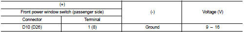
(): RHD models Is the inspection result normal? YES >> INSPECTION END
NO >> GO TO 2.
2.CHECK FRONT POWER WINDOW SWITCH (PASSENGER SIDE) POWER SUPPLY CIRCUIT
1. Turn ignition switch OFF.
2. Disconnect BCM connector.
3. Check continuity between BCM harness connector and front power window switch (passenger side) harness connector.
[With Intelligent Key]
![[Without Intelligent Key]](images/books/335/51/6.html68.jpg)
[Without Intelligent Key]
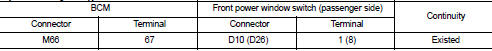
(): RHD models
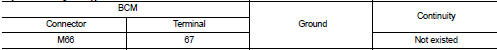
4. Check continuity between BCM harness connector and ground.
[With Intelligent Key]
![[Without Intelligent Key]](images/books/335/51/6.html74.jpg)
[Without Intelligent Key]
Is the inspection result normal? YES >> Replace BCM. Refer to BCS-93, "Removal and Installation" (with Intelligent Key) or BCS-161, "Removal and Installation" (without Intelligent Key).
NO >> Repair or replace harness.
Rear power window switch
REAR POWER WINDOW SWITCH : Diagnosis Procedure
1.CHECK REAR POWER WINDOW SWITCH POWER SUPPLY
1. Turn ignition switch OFF.
2. Disconnect rear power window switch connector.
3. Turn ignition switch ON.
4. Check voltage between rear power window switch harness connector and ground.
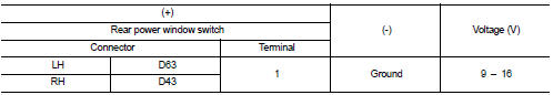
Is the inspection result normal? YES >> INSPECTION END
NO >> GO TO 2.
2.CHECK REAR POWER WINDOW SWITCH POWER SUPPLY CIRCUIT
1. Turn ignition switch OFF.
2. Disconnect BCM connector.
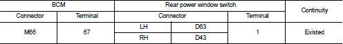
3. Check continuity between BCM harness connector and rear power window switch harness connector.
[With Intelligent Key]
![[Without Intelligent Key]](images/books/335/51/6.html92.jpg)
[Without Intelligent Key]
4. Check continuity between BCM harness connector and ground.
[With Intelligent Key]
![[Without Intelligent Key]](images/books/335/51/6.html107.jpg)
[Without Intelligent Key]
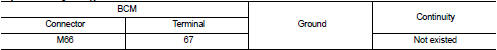
Is the inspection result normal? YES >> Replace BCM. Refer to BCS-93, "Removal and Installation" (with Intelligent Key) or BCS-161, "Removal and Installation" (without Intelligent Key).
NO >> Repair or replace harness.

 Front power window switch (passenger side)
Component Function Check
1. CHECK FRONT POWER WINDOW SWITCH (PASSENGER SIDE) FUNCTION
Check front power window motor (passenger side) operation with front power
window switch (passenger side).
...
Other materials:
B1179 lap Pre-tensioner RH
DTC Logic
DTC CONFIRMATION PROCEDURE
1.CHECK SELF-DIAGNOSTIC RESULT
With CONSULT-III
1. Turn ignition switch ON.
2. Perform тАЬSelf Diagnostic ResultтАЭ mode of тАЬAIR BAGтАЭ using CONSULT-III.
Without CONSULT-III
1. Turn ignition switch ON.
2. Check the air bag warning lamp status. Refe ...
B1066, B1071 passenger air bag module
DTC Logic
DTC DETECTION LOGIC
DTC CONFIRMATION PROCEDURE
1.CHECK SELF-DIAG RESULT
With CONSULT-III
1. Turn ignition switch ON.
2. Perform тАЬSelf Diagnostic ResultтАЭ mode of тАЬAIR BAGтАЭ using CONSULT-III.
Without CONSULT-III
1. Turn ignition switch ON.
2. Check the air bag warning la ...
P1611 ID discord, IMMU-ECM
DTC Logic
DTC DETECTION LOGIC
DTC CONFIRMATION PROCEDURE
1.PERFORM DTC CONFIRMATION PROCEDURE
1. Turn ignition switch ON.
2. Check DTC in тАЬSelf Diagnostic ResultтАЭ mode of тАЬENGINEтАЭ using CONSULT-III.
Is DTC detected?
YES >> Refer to SEC-193, "Diagnosis Procedure".
...
