Nissan Juke Service and Repair Manual : Cylinder head
Exploded View

1. Camshaft sprocket
2. Cylinder head suspended bracket
3. Valve lifter
4. Valve rotator
5. Valve spring retainer
6. Valve spring
7. Exhaust valve
8. Intake valve
9. Valve collet
10. Cap
11. Rear engine slinger
12. Cylinder head gasket
13. Cylinder head
14. Camshaft
15. Front engine slinger
16. Camshaft bracket
17. Oil seal
A : Refer to EM-311. B : Refer to EM-311
 : N·m (kg-m, ft-lb)
 : Always replace after every
disassembly.
 : Should be lubricated with oil.
 : Select with proper thickness.
CAUTION:
Apply new engine oil to parts marked in illustration before installation.
Removal and Installation
REMOVAL
1. Remove the following parts.
• Battery ground cable
• Engine undercover
• RH front wheel
2. Remove fender protector RH.
3. Drain engine coolant. Refer to CO-62, "Draining".
CAUTION
:
Perform when engine is cold.
4. Remove air cleaner case. Refer to EM-280, "Exploded View".
5. Remove radiator upper hose. Refer to CO-66, "Exploded View".
6. Disconnect fuel feed tube and return tube from high pressure supply pump. Refer to EM-298, "Exploded View".
7. Remove oil level gauge guide.
8. Remove harnesses and connectors.
9. Remove heater hoses.
10. Remove turbocharger assembly. Refer to EM-284, "Exploded View".
11. Remove drive belt. Refer to EM-276, "Removal and Installation".
12. Remove rocker cover. Refer to EM-300, "Exploded View".
13. Support underneath of engine by setting a manual lift table caddy (commercial service tool) or equivalent tool.
CAUTION:
Put a piece of wood or something similar as supporting surface, secure a
completely stable condition.
14. Remove timing belt. Refer to EM-302, "Exploded View".
15. Remove engine support bar.
CAUTION:
During the removal operation, always be careful to prevent engine moves downward
from the
vehicle.
16. Remove cylinder head bolt in the reverse order as shown.

17. Remove cylinder head assembly.
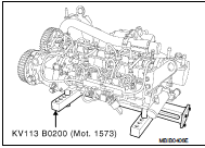
18. Place the cylinder head on Tool KV113B0200 (Mot. 1573) (Commercial service tool) or equivalent tool.
CAUTION:
Pay strict attention to the rules regarding cleanliness. Refer
to EM-263, "Precaution for Diesel Equipment".
19. Remove high pressure supply pump and related parts. Refer to EM-294, "Exploded View", EM-298, "Exploded View".
20. Remove the injectors (by marking them in relation to their cylinder), glow plugs using Tool KV113E0010 (Mot. 1566) (Commercial service tool) or equivalent tool, and rear engine slinger.

21. Remove the vacuum pump and water outlet.

22. Remove the air inlet pipe (1), front engine slinger (2), EGR unit (4), and exhaust manifold (3).

23. Remove the camshaft pulley using sprocket holder [SST: — (Mot. 1606-A)] (A).

24. Remove the camshaft brackets.

25. Remove the tappets, noting their position.

26. Compress the valve springs using the valve lifter.
Remove the keys, upper cups and springs.

NOTE:
Before removing the valves and the valve stem seals, it is
vital to measure position “H” of one of the old seals in relation
to the cylinder head using Tool KV113B0180 (Mot. 1511-
01) (Commercial service tool) or equivalent tool.

27. Install the push rod (A) of Tool KV113B0180 (Mot. 1511-01) (Commercial service tool) or equivalent tool on the valve stem seal.
NOTE:
The inner diameter of the push rod must be identical to that
of the valve. In addition, the bottom of the push rod must
come into contact with the metal upper section of the valve
stem seal.

28. Install the guide tube (B) over the push rod until the guide tube comes into contact with the cylinder head, locking the push rod with the knurled wheel.
29. Remove the guide tube assembly plus push rod, being careful not to loosen the knurled wheel.
30. Remove the valves and valve guide seals using the Tool KV113B0090 (Mot. 1335) (Commercial service tool) or equivalent tool.

ASSEMBLY OF THE CYLINDER HEAD
1. Install new valves and grind them gently into their respective seats. Clean all the parts thoroughly, mark them for identification purposes, then carry out the refitting operation.
Lubricate the inside of the valve guide.
• It is imperative to fit the valve stem seals using Tool KV113B0180 (Mot. 1511-01) (Commercial service tool) or equivalent tool.
NOTE
:
Never lubricate the valve stem seals before fitting them.

New Valve Stem Seals
1. Place the valve in the cylinder head.
2. Place the barrel of Tool KV113B0180 (Mot. 1511-01) (Commercial service tool) or equivalent tool over the valve stem (the inner diameter of the barrel must be identical to the diameter of the valve stem).
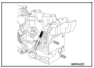
3. Keep the valve pressed against its seat.
4. Place the valve stem seal (not lubricated) over the tool barrel.

5. Push the valve stem seal past the tool barrel, then withdraw the barrel.
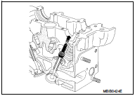
6. Place the guide tube plus push rod assembly on the valve stem seal.
7. Push the valve stem seal down by tapping the top of the sleeve with the palm of your hand until the guide tube reaches the cylinder head.
8. Repeat these operations for all the valves.

9. Install the valve springs and upper cups using valve spring compressor.
10. Install the keys using tweezers.

11. Check the valve protrusion using KV113B0040 (Mot. 251-01) (Commercial service tool) or equivalent tool and KV113B0050 (Mot. 252-01) (Commercial service tool) or equivalent tool as shown.
Valve protrusion : −0.07 to 0.07 mm (−0.0028 to 0.0028 in)

Camshaft Seal
• This engine can be fitted with two different types of seals.
Old and new seals are easily recognized.
1. The old rubber seal is installed with a spring (A) and has a “V”- shaped sealing lip (B).

2. The new rubber seal has a flat sealing lip (C) and a protector (D) which also assists in installing the seal to the engine.

3. Screw the shouldered rod of Tool KV113B0230 (Mot. 1632) onto the stud of the camshaft.
4. Install the old seal on the camshaft.

5. For the new seal, put the protector with the seal on the camshaft, taking care not to touch the seal.
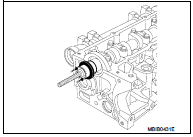
6. Install the cover (E) and the collar nut (F) of Tool KV113B0230 (Mot. 1632).
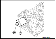
7. Screw the collar nut until the cover reaches the cylinder head.
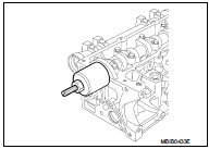
8. Remove the nut, the cover, the protector and the shouldered rod.
9. Install the camshaft pulley, and tighten the new nut as follows: a. Tighten the new nut.
 : 30 N·m (3.1 kg-m, 22 ft-lb)
b. Turn the bolt 86 degrees clockwise (angle tightening) using sprocket holder [SST: - (Mot. 1606-A)] (A).

10. Install the vacuum pump with a new gasket
 : 21 N·m (2.1 kg-m, 15 ft-lb)
11. Install water outlet unit with a new gasket.
 : 11 N·m (1.1 kg-m, 8 ft-lb)

12. Install the exhaust manifold with new gasket. Tighten the bolts in the numerical order as shown.
 : 26 N·m (2.7 kg-m, 19 ft-lb)

13. Install the EGR unit with new clips. Tighten the mounting bolts of the valve to a torque of 21 N·m (2.1 kgm, 15 ft-lb), then tighten the clips of the pipe using Tool KV113B0190 (Mot. 1567).
14. Install the air inlet pipe with a new seal.
15. Install the front engine slinger.
16. Clean the injector sockets and the injector bodies, as well as their brackets using a lint-free cloth (use the wipes recommended for this purpose) dipped in clean solvent.
Dry off using a different new wipe.
Replace the compression washer with a new washer.
17. Install the injectors (using the marks made during removal).
 : 28 N·m (2.9 kg-m, 21 ft-lb)
18. Install the glow plugs.
 : 15 N·m (1.5 kg-m, 11 ft-lb): 15
N·m (1.5 kg-m, 11 ft-lb)

19. Install the rear engine slinger.19. Install the rear engine slinger.
20. Install high pressure supply pump and related parts. Refer to EM-294, "Exploded View", EM-298, "Exploded View".
20. Install high pressure supply pump and related parts. Refer to EM-294, "Exploded View", EM-298, "Exploded View".
INSTALLATION
• Install in the reverse order of removal paying attention to the following.
INSTALLATION OF THE CYLINDER HEAD
1. Position the pistons at mid-stroke.
2. Install the cylinder head gasket using the centering dowels of the cylinder block.
3. Tighten the cylinder head to the following procedure.
CAUTION:
All bolts must always be changed after removal. Never oil the new bolts.
NOTE:
Use a syringe to remove any oil which may have entered the cylinder head mounting bolt holes to achieve correct tightening of the bolts.
a. Tighten all the bolts in the numerical order as shown.
 : 25 N·m (2.6 kg-m, 18 ft-lb)
b. Check that all the bolts are correctly tightened to 25 N·m (2.6 kgm, 18 ft-lb), then angle tightening of 245 to 265 degrees.
CAUTION:
• Use an angle wrench (special service tool) to check tightening
angle.
• Never retighten the cylinder head bolts after preforming this procedure.

NOTE:
The gasket faces (cylinder head and rocker cover) must be clean, dry and free
from grease (in particular,
remove finger marks).
4. Lay four beads (A) of liquid gasket, with a diameter of 2 mm (0.08 in).
• Use Genuine Liquid Gasket or equivalent.

5. Install the rocker cover, tighten the bolts in numerical order as shown.
 : Engine front
 : 12 N·m (1.2 kg-m, 9 ft-lb)

6. Put new seals on the pipe ends and install the turbocharger oil return pipe.
7. Install the turbocharger.
 : 26 N·m (2.7 kg-m, 19 ft-lb)
8. Install the turbocharger oil supply pipe.
9. Tighten the bolts of the turbocharger oil return pipe.
 : 12 N·m (1.2 kg-m, 9 ft-lb)

10. Tighten the nut and the bolt of the turbocharger oil supply pipe (A).
 : 23 N·m (2.3 kg-m, 17 ft-lb)

11. Install the oil vapor rebreathing pipe.
12. Install the new turbocharger air ducts.
13. Install the inner timing cover.
14. Install the timing tensioner.

Cleaning
• It is very important not to scratch the gasket faces of any aluminium components.
• Use suitable tool to dissolve any part of the seal which remains stuck to the metal surface.
• Apply the dissolving product to the part to be cleaned, wait approximately 10 minutes, then remove it using a wooden spatula.
• Wear gloves while carrying out this operation.
• Do not allow this dissolving product to drip on to the paintwork.
• Great care should be taken when performing this operation, to prevent foreign objects from entering the pipes taking oil under pressure to the camshafts (pipes in both the cylinder head and its cover) and the oil return pipes.
• Failure to follow these instructions could lead to the blocking of the oilways, resulting in rapid and serious damage to the engine.
Inspection
INSPECTION AFTER REMOVAL
GASKET FACE
• Inspect mating surface bow using a ruler and a set of shims.
Maximum bow : 0.05 mm (0.0020 in)
• Test the cylinder head to detect possible cracks using the cylinder head test tools (comprising a tray and a kit suited to the cylinder head, plug, sealing plate and blanking plate). The approval number of the cylinder head test container (commercial service tool) is 664000.
CAMSHAFT END PLAY
NOTE
:
Set the dial gauge to the cylinder head and inspect following dimensions:
Outer diameter : 18 mm (0.71 in) Height : 15 mm (0.59 in)
1. Install the camshaft.
2. Install the camshaft brackets (positioning them correctly with bracket 1 on the flywheel end), then tighten the bolts to a torque of 11 N·m (1.1 kg-m, 8 ft-lb).
Check the end play, which must be between 0.08 mm (0.0031 in) and 0.178 mm (0.0070 in).
Remove the camshaft brackets and the camshaft.

THICKNESS OF THE CYLINDER HEAD GASKET
• The thickness of the cylinder head gasket is measured at (A):
Thickness : 0.75 - 0.81 mm (0.0295 - 0.0319 in)

VALVE DIMENSIONS
Stem diameter:
Intake : 5.969 - 5.985 mm (0.2350 - 0.2356 in)
Exhaust : 5.955 - 5.971 mm (0.2344 - 0.2351 in)
Face angle:
Intake and exhaust
: 90°
Head diameter:
Intake : 33.38 - 33.62 mm (1.3142 - 1.3236 in)
Exhaust : 28.88 - 29.12 mm (1.1370 - 1.1465 in)
Valve length:
Intake : 100.73 - 101.17 mm (3.9657 - 3.9831 in)
Exhaust : 100.53 - 100.97 mm (3.9579 - 3.9752 in)
Max. valve lift:
Intake : 8.015 mm (0.3156 in)
Exhaust : 8.595 mm (0.3384 in)
Protrusion of valves in relation to the cylinder head gasket face:
Intake and exhaust
: −0.7 to 0.7 mm (−0.028 to 0.028 in)
VALVE SEAT
Seat angle (α):
Intake
and exhaust
: 89°30′
Contacting width (X):
Intake
and exhaust
: 1.8 mm (0.071 in)
Seat outer diameter (D):
Intake : 34.444 - 34.460 mm (1.3561 - 1.3567 in)
Exhaust : 30.034 - 30.050 mm (1.1824 - 1.1831 in)
Diameter of the housing in the cylinder head:
Intake : 34.444 - 34.474 mm (1.3561 - 1.3572 in)
Exhaust : 29.955 - 29.985 mm (1.1793 - 1.1805 in)

VALVE GUIDE
Length:
Intake and
exhaust
: 40.35 - 40.65 mm (1.5886 - 1.6004 in)
Guide outer diameter:
Standard : 11.044 - 11.062 mm (0.4348 - 0.4355 in)
Guide inner diameter:
Intake and exhaust
Not machined
: 5.50 - 5.62 mm (0.2165 - 0.2213 in)
Machined* : 6.000 - 6.018 mm (0.2362 - 0.2369 in)
* This dimension is measured with the guide fitted in the cylinder head.
Diameter of the housing in the cylinder head: Standard : 10.9925 - 11.0075 mm (0.4328 - 0.4334 in)
The intake and exhaust guides have valve stem seals which must be changed each time the valves are removed.
It is imperative to fit the valve stem seals using Tool KV113B0180 (Mot. 1511-01) (Commercial service tool) or equivalent tool.
NOTE: Do not lubricate the valve stem seals before fitting them.
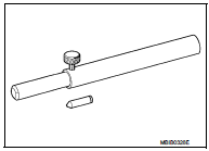

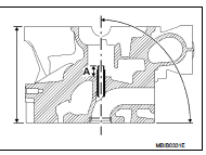
Angle of the intake and exhaust guides (in degrees) Intake and exhaust : α = 90

Position of the intake and exhaust valve guides Intake : A = 14 mm (0.55 in) Exhaust : A = 14.2 mm (0.559 in)
VALVE SPRING
The valve springs are tapered (ensure the correct direction of fitting).
Free height: : 43.31 mm (1.7051 in)
Length under a load of
230 N (23.5 kg, 51.7 lb) : 33.80 mm (1.3307 in)
500 N (51.0 kg, 112.4 lb) : 24.80 mm (0.9764 in)
Joined spires: : 23.40 mm (0.9213 in)
Wire diameter: : 3.45 mm (0.1358 in)
Inner diameter:
Bottom : 18.78 - 18.82 mm
(0.7394 - 0.7409 in)
Top : 13.90 - 14.30 mm
(0.5472 - 0.5630 in)
Outer diameter:
Bottom : 25.50 - 25.90 mm
(1.0039 - 1.0197 in)
Top : 20.8 - 21.2 mm (0.819
- 0.835 in)

WARNING:
This engine does not have any valve spring lower washers.
PISTON
Piston outer diameter : 34.965 - 34.985 mm (1.3766 - 1.3774 in) Diameter of the housing in the cylinder head : 35.00 - 35.04 mm (1.3780 - 1.3795 in)
CAMSHAFT
End play : 0.08 - 0.178 mm (0.0031 - 0.0070 in)
Number of bearings : 6
Diameter of the camshaft bearings
On the camshaft:
Bearings 1, 2, 3, 4, 5 : 24.979 - 24.999 mm (0.9834 - 0.9842 in)
Bearing 6 : 27.979 - 27.999 mm (1.1015 - 1.1023 in)
On the cylinder head:
Bearings 1, 2, 3, 4, 5 : 25.04 - 25.06 mm (0.9858 - 0.9866 in)
Bearing 6 : 28.04 - 28.06 mm (1.1039 - 1.1047 in)
Timing diagram
Intake opening retard * : −9
Intake closing retard : 20
Exhaust opening advance : 27
Exhaust closing advance ** : −7
* As the intake opening retard is negative, the valve is opened after TDC.
** As the exhaust closing advance is negative, the valve is closed before TDC.

 Timing belt
Exploded View
1. Timing belt inner cover
2. Timing belt
3. Camshaft sprocket
4. Timing belt tensioner
5. Timing belt upper cover
6. Timing belt lower cover
7. Cylinder head suspended brac ...
 Unit removal and installation
Engine assembly
Exploded View
1. Engine torque rod
2. Engine mounting insulator
3. Engine mounting stay
4. Transaxle mounting stay
5. Engine mounting rear bracket
6. Transaxle torque rod ...
Other materials:
P1612 chain of ECM-IMMU
DTC Logic
DTC DETECTION LOGIC
NOTE:
• If DTC P1612 is displayed with DTC U1000 (for BCM), first perform the trouble
diagnosis for DTC U1000.
Refer to BCS-153, "DTC Logic".
• If DTC P1612 is displayed with DTC U1010 (for BCM), first perform the trouble
diagnosis for DTC U1010.
...
Door does not lock/unlock with keyfob
Diagnosis Procedure
1.CHECK POWER DOOR LOCK OPERATION
Check power door lock operation.
Does door lock/unlock with door lock and unlock switch?
YES >> GO TO 2.
NO >> Go to DLK-415, "ALL DOOR : Diagnosis Procedure".
2.CHECK REMOTE KEYLESS ENTRY RECEIVER
Check remote ...
P0131 A/F sensor 1
DTC Logic
DTC DETECTION LOGIC
To judge the malfunction, the diagnosis checks that the A/F signal computed
by ECM from the A/F sensor 1
signal is not inordinately low.
DTC CONFIRMATION PROCEDURE
1.PRECONDITIONING
If DTC Confirmation Procedure has been previously conducted, always turn
ign ...
